Technology for the Next-Generation UAVs Applied to the UAS-S45
Purchased from Gettyimages. Copyright.
In recent years, the morphing wing concept has attracted the attention of many researchers in the aeronautics industry due to its promising advantages in aerodynamics and flight dynamics. Morphing technology benefits the aviation industry in terms of cost-saving economic policies and contributes positively to the goals of green aviation technologies by reducing carbon emissions. In this study, we performed an aerodynamic optimization for the morphing trailing edge of a unmanned surveillance aerial system (drone), UAS-S45, to analyze the optimization dependency on the parametrization method. For this purpose, the Free-Form Deformation parametrization technique was used to examine the influence of initial parametrization conditions on the optimization results. Results indicate that the number of control points significantly affects the optimization process, in particular convergence, objective function, and deformation feasibility. Keywords: Deformative parametrization, UAS-S45, Morphing flap, FFD parametrization, DAFoam optimization framework, OpenFOAM
Nature-Inspired Technology for Next-Generation Aircraft
Nature always has the best solutions for the challenges we face in the modern world. Our physical environment has evolved over millions of years, and today we see an optimized version of its functionality; therefore, we can apply these highly efficient solutions to the engineering problems of our modern world. Considering birds and other living flying creatures, we can observe the most efficient flight that nature has optimized over millions of years. By mimicking these living flying creatures and applying their flight physics to our human-made aircraft, one can solve all the problems of the aeronautics industry. The result would reflect highly efficient aircraft dynamics whose aerodynamic efficiency would outperform conventional aircraft dynamics in reducing drag and, more importantly, reducing fuel consumption, thereby minimizing carbon emissions and making aircraft more environmentally friendly.
The morphing wing is one of the promising technologies by which the mentioned goal will be achieved, allowing us to benefit from highly efficient aircraft for the next-generation aerospace industry. Morphing technology is studied for each flight condition, such as take-off, climb, cruise flight, rolling maneuver, and landing. For each flight condition, different morphing strategies have been proposed, such as sweep [1], twist [2], winglet [3], span morphing [4] camber [5], leading edge [6,7], and upper surface morphing [8-16]. In recent years, several aerodynamic optimizations using different optimization algorithms and parametrization methods have been performed in the Active Controls, Avionics, and Aeroservoelasticity Research Laboratory (LARCASE). Table 1 shows these studies in detail.
Table 1. List of research works conducted at the LARCASE using different optimization algorithms and parametrization methods.
Aerodynamic shape optimization has recently been the focus of many studies in aeronautics due to its significant contribution in improving aircraft and UAV performance. In aerodynamic shape optimization, the choice of an adequate parametrization method to change the wing shape is of paramount importance before starting the optimization process, meaning that the more realistically the wing shape can be parameterized, the more accurate and robust are the optimization results. The overall optimization process—including computation time, robustness and solution precision—strongly depends on the chosen parametrization technique [1].
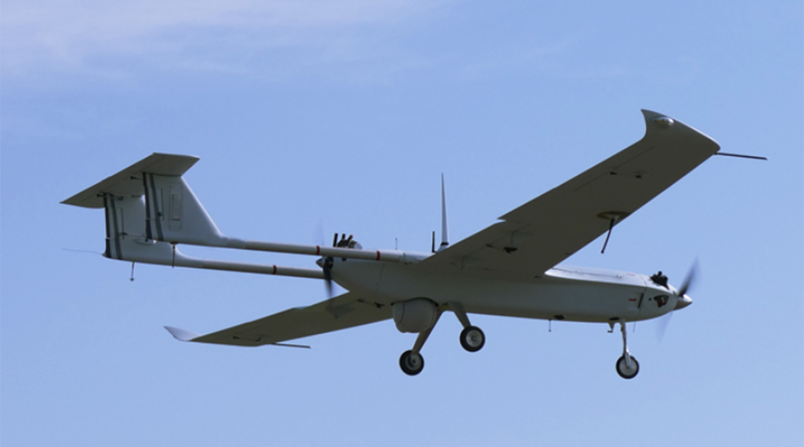
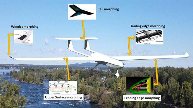
In the present study, an aerodynamic shape optimization was performed on the morphing trailing edge. Among the morphing configurations, trailing edge morphing is the most commonly studied, due to its influence on flight performance, especially in cruise flight. In this study, the trailing edge morphing of a UAS-S45 airfoil was optimized using the Free-Form Deformation technique (FFD) parametrization technique. The UAS-S45 is an unmanned aerial surveillance system designed and manufactured by Hydra Technologies in Mexico. Figure 1 shows the UAS-S45 with different morphing configurations obtained from studies conducted at the LARCASE.
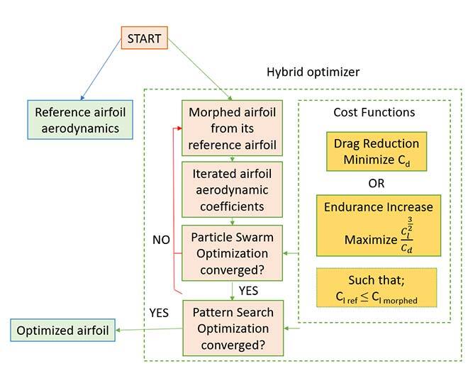
Figure1. Morphing studies and optimizations conducted on the UAS-S45 at LARCASE.
Overview of the Optimization Strategy
In this study, we used a method to find the optimal shape of the morphing trailing edge of the UAS-S45 airfoil under cruise flight conditions. To perform this optimization, we needed to generate or parameterize the airfoil and import it from physical space to modeling space by mapping it into mathematical formulations. To do this, we used the FFD technique, and the main purpose of this study was to analyze the parametrization method influence on the optimization results. The optimization was based on a gradient-based algorithm that couples a new Python optimization algorithm with a high-fidelity OpenFOAM flow solver. The overall optimization framework is illustrated in Figure 2.
Figure 2. Optimization framework.
FFD Parametrization Technique
In this mapping technique, the geometry of a given size is embedded in a lattice, called a FFD block, with its corresponding control points. The lattice consists of B-spline control points which, when altered, change the shape of the embedded body. The number of control points and their displacements depend on the geometry and deformation zone of the body. In this study, to examine the FFD parametrization in terms of number of control points, five sets of FFD blocks with different numbers of control points for the same block topology and the same morphing configuration were analyzed. Figure 3 shows the UAS-S45 airfoil embedded in the FFD block. Two FFD blocks were used, one for the undeformed part (white block: 70% of the chord length) and the other for its morphing trailing edge (red block: 30% of the chord length). As depicted in Fig. 3, the control points shown in green are the ones that are free to move in a vertical downward direction to increase the lift-to-drag ratio, while the rest (those not coloured) are constrained to zero motion in every direction.
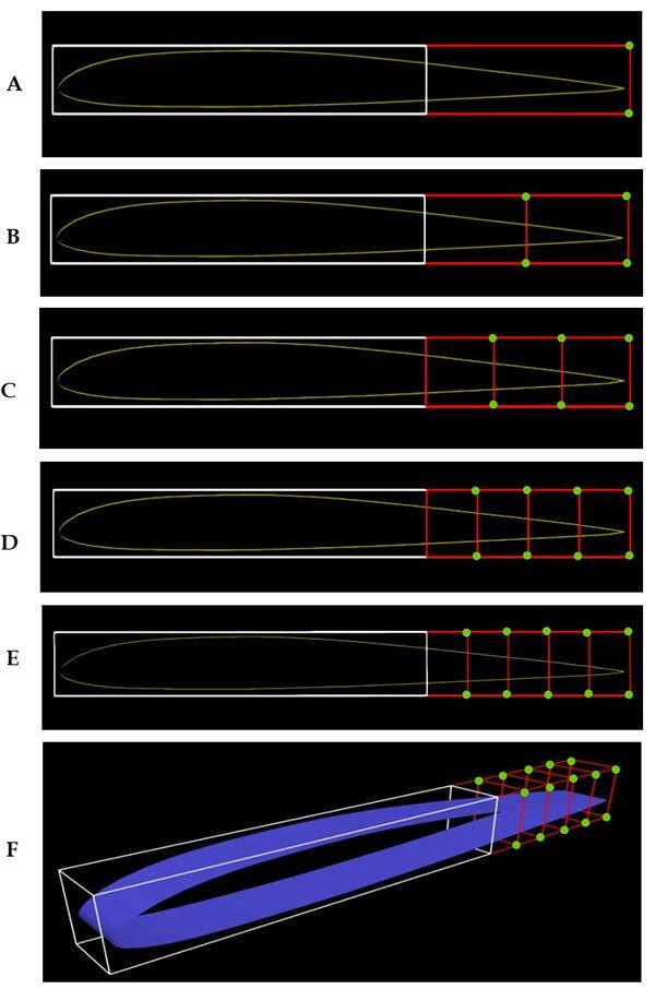
Figure 3. UAS-S45 airfoil embedded in FFD blocks for five cases with A) 8, B) 12, C) 16, D) 20, E) 24 control points from a side view, and F) the FFD block with 24 control points in an isometric view.
Key Findings
Optimization results were compared for five cases in which different numbers of control points were considered. Various criteria, including convergence time, number of iterations, optimality errors, and objective function values were compared for different numbers of control points. Figure 4 (A-B) shows the optimality error of the optimization process for each case. In Fig. 4-A, for cases 1 to 3, the number of control points is lower than cases 4 and 5, and convergence is reached with a low number of iterations with an error of the order of 10^-6 . However, as shown in Table 3, for cases 4 and 5 (Fig. 4-B), good convergence is not achieved even after 50 iterations and the error is of the order of 10^-2 and 10^-3 for cases 4 and 5, respectively. Table 3 shows the comparison of five cases in terms of convergence time, number of iterations, optimality, and lift-to-drag ratio (Cl/Cd).
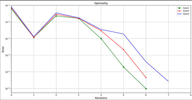
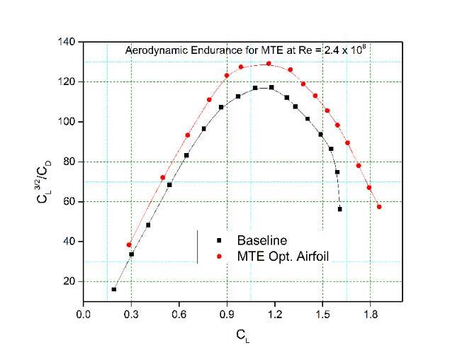
Figure 4. Errors in the optimization process, A) Cases 1, 2 and 3, B) Cases 4 and 5.
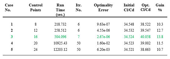
Table 3. Comparison of the optimization results for five cases
As shown in Table 3, as the number of control points increases, so does the number of iterations, computation time and error, leading to inaccurate results. By considering the objective function, the maximum value of the lift-to-drag ratio is obtained in case 3, corresponding to a 13.8% gain. If all criteria are considered, it is evident that case 3 with 16 control points gives the best results in terms of optimality error, convergence time, and Cl/Cd maximization (objective function).
Figure 5 shows the UAS-S45 airfoil after morphing trailing edge optimization for all five cases. In case 1, the one with the least number of control points (8), the trailing edge shows a sharp bending, like that of a hinged flap, but as the number of control points increases, the deformation becomes smoother. However, when the number of control points exceeds 16 (cases 4 and 5), the smooth deformation of the trailing edge turns into a wave-like deformation (Fig. 5). Therefore, case 3 is the best in terms of deformation feasibility.
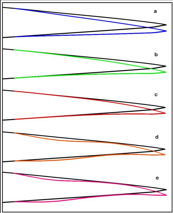
Figure 5. Illustration of the morphing trailing edge of the UAS-S45 airfoil for a) case 1, b) case 2, c) case 3, d) case 4, and e) case 5, after optimization.
Conclusion
A high-fidelity aerodynamic optimization of a morphing trailing edge was performed in this study using free-form deformation parametrization. The study was conducted for five cases, distinct in terms of the number of FFD control points. The primary purpose of this study was to show the influence of FFD parametrization flexibility in terms of control points and to show how it would affect the final optimization results. The study of five cases showed that these ultimate optimization results were directly influenced by the choice of the number of control points, where too few control points (less than 16) led to unsmooth deformation and less objective function improvement. This observation means that a low number of control points restricts morphing capability. On the other hand, a higher number of control points (higher than 16) led to undesirable wavy deformations, which are impractical from the mechanism and manufacturing perspectives; moreover, a higher number of control points did not show very good optimization accuracy, and satisfactory convergence was not achieved. We have shown that the influence of the number of control points on the optimization results was substantial, and had a direct impact on them. There should be a trade-off in finding the optimal number of control points before starting optimization by analyzing three parameters: computation time, solution optimality, and improvement rate of the objective function.
Additional Information
For more information on this research, please read the following research paper:
Negahban, M.H., Bashir M., Botez, R.M., “Free-Form Deformation Parametrization on the Aerodynamic Optimization of Morphing Trailing Edge,” Journal of Applied Mechanics, 4(1), 2023, pp. 304-316.