The More Electric Aircraft—The Future of the Aeronautic Industry

The featured image was bought from Istock.com. Copyrights.
Over the last decade, the aerospace design community has been embracing the utilization of electricity to provide increasingly larger proportions of the power requirements for developed aircraft. Driven primarily by the desire to enhance fuel economy and reduce the environmental footprint of powered flight, the trend towards greater electrical usage on modern aircraft has led to several research projects focused on developing new and innovative Propulsion and Power System architectures. The aim of the research is to develop a simulation platform for the electric power distribution system. Developing numerical models and simulation tools is necessary to create more efficient electrical system designs. Simulation tools offer limitless solutions in increasing system robustness while reducing expensive aircraft flight tests. It could also be possible to study a large number of operational scenarios and to detect failure conditions.
Introduction
Over the last decade, the aerospace design community has been embracing the utilization of electricity to provide increasingly larger proportions of power requirements for developed aircraft. Driven primarily by the desire to enhance fuel economy and reduce the environmental footprint of powered flight, the trend towards greater electrical usage on modern aircraft has led to several research projects focused on developing new and innovative Propulsion and Power System architectures.
The more-electric concept is a new technological target for aerospace manufacturers, which involves reducing fuel consumption, improving power efficiency, as well as the possibility of significantly reducing aircraft weight. In conventional aircraft, multiple systems are based on the use of hydraulic, mechanical, pneumatic and electrical energy sources. These types of energy have different drawbacks like efficiency, emissions, reliability and maintenance costs, especially with hydraulic and pneumatic systems. The goal of the More Electric Aircraft concept is to replace pneumatic and mechanical systems with electric systems in order to reduce weight and size, and improve fuel efficiency. It is necessary to increase the efficiency of electrical systems and components in aircraft to generate, distribute and utilize electrical power.
Electric Propulsion Architectures
Electrical propulsion in aircraft could reduce carbon emissions, but only if new technologies meet specific criteria: required power, weight, and reliability. Six different electric propulsion architectures are considered [1]. As shown in the following figures, one is all electric, three are hybrid electric, and two are turboelectric [2].
- All electric
- Hybrid electric
- Parallel hybrid
- Series hybrid
- Series/parallel partial hybrid
- Turboelectric
- Full turboelectric
- Partial turboelectric
These six architectures are based on different electric technologies: batteries, motors, generators and converters. The only source of propulsion power in all-electric systems are batteries instead of gas (Figure 1); turbine engines are used in the hybrid systems for propulsion and to charge batteries. However, the batteries provide energy for propulsion during specific phases of flight.
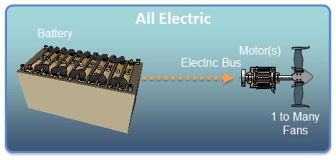
Figure 1 All Electric architecture
In a parallel hybrid topology (Figure 2), a battery provides energy to the electrical generator and a turbine engine (turbofan) is placed on the shaft that directly controls a fan. However, the turbofan is powered by fuel. It is also possible, at any given time, to choose between these two types of energy to provide propulsion.
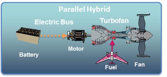
Figure 2 Parallel Hybrid architecture
In a series hybrid architecture (Figure 3), the gas turbine or turboshaft drives an electric generator, transforming mechanical energy into electrical energy, providing power to the motors and charging the batteries. The fans are mechanically mounted on the electric motor shafts. This type of architecture represents the distributed propulsion concept because it uses several motors and fans.
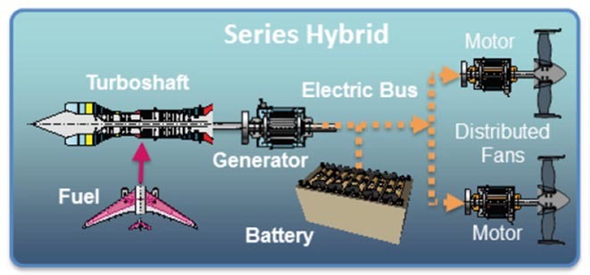
Figure 3 Series Hybrid architecture
The series/parallel-partial hybrid is a combination of parallel and series hybrid configurations (Figure 4). A gas turbine or turbofan is powered by fuel and drives an electric generator. The turbine shaft includes a fan and an electric generator. The turbine-driven generator delivers energy to the batteries or motor and the batteries can also power these motors if needed. Propulsion is generated by the fan on the turbofan, with the distributed fans mounted on the multiple motors or both.
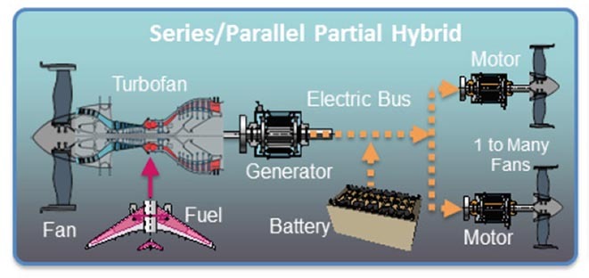
Figure 4: Series/Parallel-Partial Hybrid architecture
Full and partial turboelectric architectures (Figure 5) do not use batteries for propulsion during flight. They will rather use gas turbines to directly drive one or more electric generators, which power inverters and motors. These electric motors control the distributed electric fans.
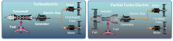
Figure 5: Full and partial turboelectric architectures
Partial turbo electric architecture uses electric motors coupled with fans, and a turbofan controlled by a gas turbine to provide the propulsion power. In the case of a full turboelectric system, only electric motors are used for propulsion. Neither architecture relies on batteries nor energy storage technologies. The controllers and electrical components in a full turboelectric system are less advanced and complex than in a partial turboelectric system. Above all, the command will be less complex to implement in a full turboelectric architecture because controlling a multiple electric motor is well-established for electrical engineers.
Turboelectric and other electric propulsion architectures are well adapted to a distributed propulsion for aircraft instead of hybrid-electric and all-electric systems. Indeed, specific power and power capacity required of batteries are very limited for long flights. Turboelectric propulsion is a promising future line of research in the development of advanced propulsion, and could reduce CO2 emissions.
Simulation of More-Electric Aircraft Power Systems
Developing tools and processes is necessary in the development of aerospace-grade Integrated Electric Propulsion Systems (IEPS) in modern aerial vehicles. The aim of our research project is to create a simulation platform for the electric power distribution system in order to analyze network stability issues, harmonic content“Harmonic is multiple of the fundamental frequency and it can be voltage and current in an electric power system are a result of non-linear electric loads. Harmonic frequencies in the power grid are a frequent cause of power quality problems. Harmonics in power systems result in increased heating in the equipment and conductors, misfiring in variable speed drives, and torque pulsations in motors. Reduction of harmonics is considered desirable.” Ref. Wikipedia, electromagnetic transients“A transient event is a short-lived burst of energy in a system caused by a sudden change of state. The source of the transient energy may be an internal event or a nearby event. The energy then couples to other parts of the system, typically appearing as a short burst of oscillation.” Ref. Wikipedia and electrical faults. The approach in the development of these simulation models in real time is divided into three phases. Figure 6 represents the different phases of a simulation.
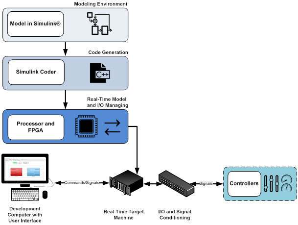
Figure 6 Simulation steps
The first step is to collect the different models required to perform the simulation. The vast majority of these models are available in the MATLAB-Simulink simulation software toolbox. Otherwise, it is necessary to develop numerical models and simulation tools to create more efficient electrical system designs—to correct design errors and to eliminate prototyping steps. These models must be as accurate and faithful as possible. By using the available data and hypothesis, power system component models are connected to show their capability to perform comprehensive simulations. Another important work in this phase will be to adjust the parameters required by these models (machine parameters, controller gains, etc.)
The second phase is to build the complete model in offline simulation“Opposite to real-time simulation.”. Offline simulation achieves several goals. The first objective is to determine the viability of the completed model by avoiding precision deterioration caused by the discretization“Discretization is the process of transferring continuous functions, models, variables, and equations into discrete counterparts. This process is usually carried out as a first step toward making them suitable for numerical evaluation and implementation on digital computers.” Ref. Wikipedia required for the real-time transition. The second objective is to study the effect of model separation“It’s an optimization step that consists to divide the global modal into sub-models to solve equations faster.”. Separation is the end of the optimization step and is required to start the computing task on multiple processors during the real-time simulation. Since the delays introduced by this separation have an impact on the simulation accuracy and stability, it is very important to study their effects thoroughly.
Once the offline simulation phase has been completed, the third and last phase is to implement the model in real time. Real-time simulation tools offer the computational speed advantage and allow to study a very large number of operational scenarios within a reduced time. It could also be possible to study large numbers of operational scenarios and detect failure conditions. Moreover, such tools can provide real-time synchronized simulations and allow interfacing with external physical equipment (hardware-in-the-loop). This type of interfacing is used to validate physical controllers, improve design and develop models through the analysis of black-box type physical device performance waveforms.
Figure 7 represents a typical simulation platform for a More Electric Aircraft Power system by combining a high-accuracy aircraft model with power system devices like power converters, generators, active and static loads.
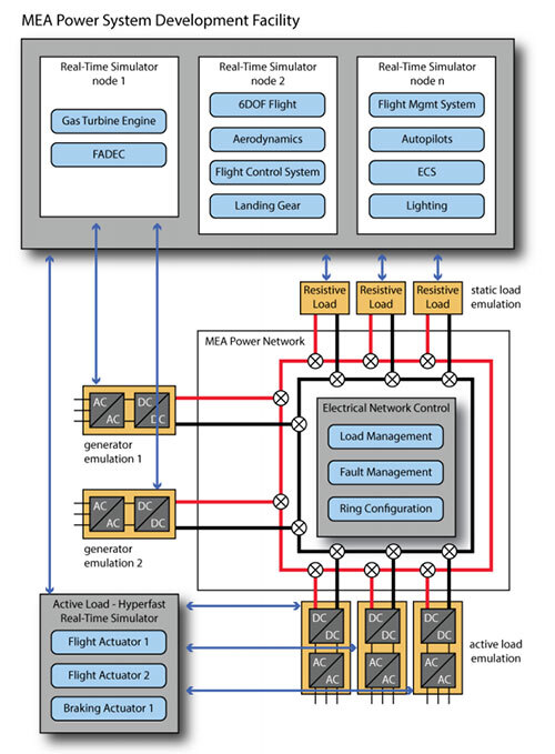
Figure 7 More Electric Aircraft Power Systems Development.