Facilitating UAV Landing Through Pose Estimation
Purchased on Istockphoto.com. Copyright.
Pose estimation is one of the most fundamental parts of an unmanned aerial vehicle (UAV) control system design. It accurately measures the coordinates and directions of a specific point: the aerial vehicle centroid, also known as the center of mass. These measurements can be translational or rotational and can serve as feedback to the control system for various tasks, including rendevous and the final landing, especially in challenging situations, such as marine environments, where the landing platform is moving with the waves.
A standard pose estimation method is the AprilTag Detection Algorithm (ATDA). In our work, range data from the sensors and AprilTag corners detected via ATDA were fused using a Camera and Range Sensor Homogeneous Fusion (CRHF) method to improve accuracy. First, we developed a calibration algorithm to model the relationship between pixels and measured ranges for all four range sensors. This relationship was then used to measure the focal length in each iteration. Next, the 2D real-world corner point locations (in X and Y directions) were calculated via homogeneous equations based on the focal length and the corner points in the pixel coordinates. Then, the landing platform’s normal vector gave the Z coordinate of the corners. Finally, the rigid body transformation technique was applied to find the actual pose of the AprilTag. The CRHF evaluation was obtained through ground truth data from simulators and ATDA.
System Design
The design included five sensors. Four were range sensors located beneath the four propellers. In addition, a downward camera with 512 × 512 resolution was attached to the drone’s mass center and range sensors.
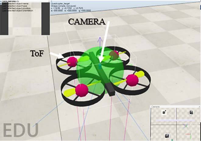
Figure 1. UAV sensor locations – CRHF-based pose estimation
In addition, detection and primary pose were determined through a landmark called AprilTag. Nowadays, landmarks, including AprilTag are used for various applications, such as object positions, orientations, and identification. Hence, they are highly effective in the robotic industry. In this research, the landmark was a pose estimation tool.
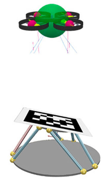
Figure 2. Placement of the AprilTag on the dynamic landing platform
Figure 2 illustrates the platform developed for the UAV landing system. The AprilTag is located on the Stewart platform dynamic system representing the ocean dynamics. The UAV attempts to measure the landmark pose, here AprilTag, to decide a suitable moment for the final landing.
Proposed Algorithm Overview
The downward camera captures the AprilTag image. Image distortion is removed with the camera’s intrinsic parameters. Then, the corner points of the AprilTag are calculated with ATDA and tracked via a Kalman Filter (KF) technique. A camera and range sensor calibration technique called CRHF calculates the AprilTag corner point locations in the camera frame in X and Y coordinates. The landing platform normal vector calculated from the four range sensors is also used to calculate the Z coordinates.

Figure 3. Overview of the entire pose estimation process, including the CRHF algorithm
These points project the relative rigid body pose of the corners with respect to the camera centroid, which is the same as the UAV centroid.
The CRHF Algorithm
The calibration technique is conducted through data collection from the camera and altitude data from the range sensors. Altitude data and the calibration pad centroid data are found at the same altitude: the images of the pads are captured at every altitude, and the pad centroids are extracted through a color segmentation technique.

Figure 4. Camera and range sensor calibration process
Hence, each range sensor data is related to the pad centroid pixels in the image. Finally, the missing ranges are calculated through the shape-preserving interpolation technique.
Developed Evaluation System
Two software, namely MATLAB and CoppeliasSim, were integrated into a Software-in-the-Loop (SIL) to develop an evaluation ecosystem. While CoppeliaSim acts as a physical world, the MATLAB session replicates the UAV computer.

Figure 5. Data transfer and calculations used in the SIL
In Figure 5, the MATLAB session calculates the pose of the landing platform using CRHF and ATDA algorithms in every iteration. The image, range, and ground truth data are collected through the CoppeliaSim session. ADTA and CRHF performances were measured via Mean Absolute Error (MAE). MAE is calculated by summing up the absolute difference between observed (or estimated) and actual value divided by the number of iterations. Two tests involving static and highly dynamic platforms were performed.
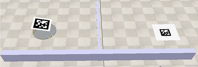
Figure 6. Designed static (right side) and dynamic (right side) landing platforms
The AprilTag is laid over a stationary ground in the static test and attached over the 6 degrees of freedom (6DoF) Stewart platform for the dynamic test bench, according to Figure 6.
Comparison Between CRHF and ATDA Algorithms
The proposed CRHF algorithm to improve ATDA was evaluated by comparing results with the ATDA technique and the ground truth data from the simulator.

Figure 7. Estimated trajectories for CRHF (blue), ground truth (green), and ATDA (red)
As inferred from the 3D trajectory plot, the CRHF significantly outperformed the ATDA technique. However, the downside of the proposed algorithm is that it involves the cost of four range sensors and weight added to the drone system. Nowadays, new technologies in range sensors reduce the cost and weight of the application, alleviating the negative aspects of CRHF.

Table 1. Performance comparison of ATDA and CRHF – Mean Absolute Error (MAE)
Table 1 demonstrates the Mean Absolute Errors for the ADTA and CRHF methods.
Additional Information
For more information on this research, please read the following paper: Sefidgar, Mohammad, and Rene Landry Jr. 2022. “Unstable Landing Platform Pose Estimation Based on Camera and Range Sensor Homogeneous Fusion (CRHF)” Drones 6, no. 3:60. https://doi.org/10.3390/drones6030060.