February 9, 2026

Why Power Grids Need Faster Reactive Power Control
Modern power grids are under increasing stress. Industrial loads, renewable energy sources, and power electronics-based equipment introduce voltage fluctuations, harmonics, and poor power factors. These issues can reduce efficiency, cause equipment overheating, and even lead to instability in the grid.
To address these challenges, utilities rely on Static Synchronous Compensators (STATCOMs). STATCOMs are power-electronic devices connected to the grid that rapidly inject or absorb reactive power, stabilizing voltages and improve power quality. However, traditional STATCOM designs tend to be bulky, expensive, and complex, especially at medium- and high-voltage levels.
This research explores how STATCOMs can be made smaller, more efficient, and more cost-effective without sacrificing performance.
The Challenge with Conventional STATCOM Converters
Most modern STATCOMs are based on Modular Multilevel Converters (MMCs). MMCs are attractive because they are modular, scalable, and produce high-quality voltage waveforms with low harmonic distortion. The main drawback is that achieving smooth voltages requires a large number of submodules, which increases:
- System size
- Component count
- Cost
- Control complexity
Simply put, better performance usually means more hardware, and that becomes a problem for large-scale deployment.
A Compact Alternative: The Z Packed U-Cell MMC
To overcome this limitation, this work introduces a STATCOM based on a Z Packed U-Cell (ZPUC) submodule integrated into an MMC structure.
Instead of generating only two voltage levels per submodule, as in conventional designs, the ZPUC submodule produces multiple voltage levels internally. This means:
- Fewer submodules are needed
- Fewer power switches per phase
- Lower losses and reduced footprint
In the proposed design, only two ZPUC submodules per arm are enough to generate a 17-level phase voltage, a level of performance that would normally require many more conventional submodules.
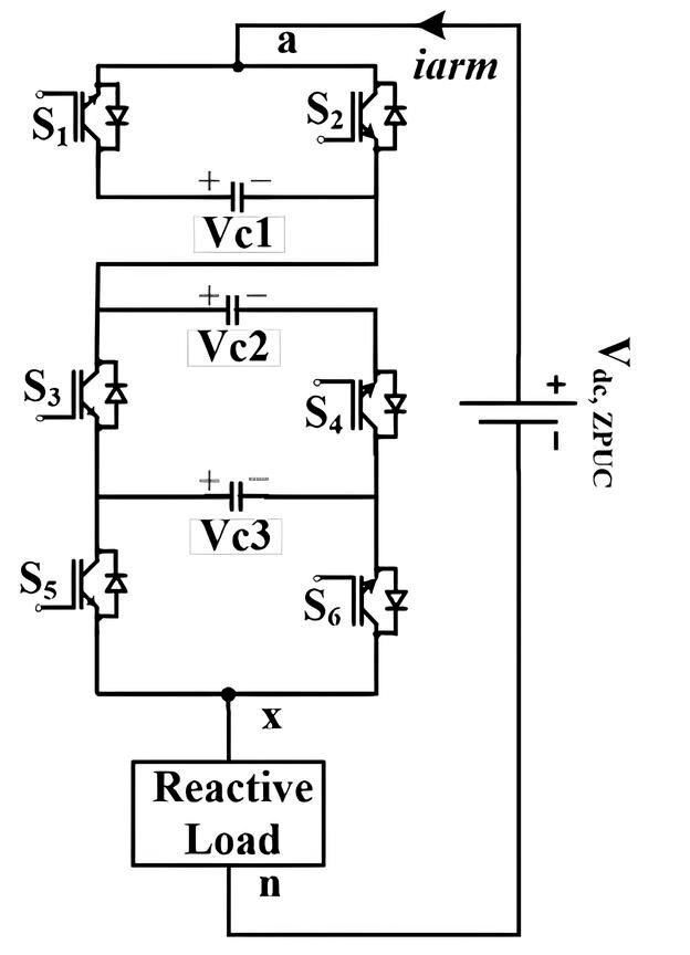
Figure 1: Conceptual diagram of the Z Packed U-Cell submodule
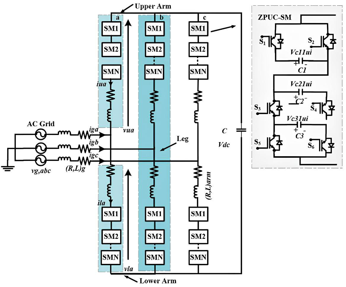
Figure 2: Overall structure of the proposed 17-level ZPUC-based MMC STATCOM
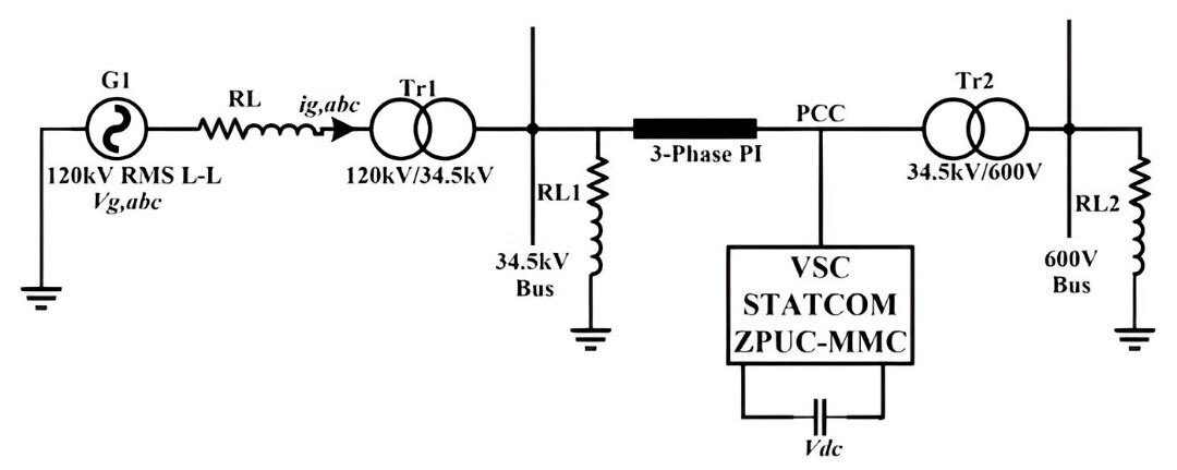
Figure 3: VSC ZPUC-MMC STATCOM connected in shunt with PCC
Built-in Voltage Balancing Without Extra Controllers
A major difficulty in multilevel converters is maintaining the balance of internal capacitor voltages. Many solutions rely on additional sensors and complex control loops.
One of the key advantages of the ZPUC-based approach is that voltage balancing is inherently achieved through the modulation strategy. By using a phase-shifted pulse-width modulation (PS-PWM) method, capacitor voltages remain naturally balanced during operation—without adding extra control layers.
This simplifies the control architecture and improves system reliability.
Why Real-Time Simulation Matters
Building a full-scale STATCOM prototype is expensive and time-consuming. To validate the proposed design, the system was tested using real-time simulation on an FPGA-based platform.
Real-time simulation allows the converter and its control system to behave exactly as they would in real hardware, but without physical risks. Compared to traditional CPU-based simulations, FPGA execution enables:
- Much smaller time steps
- Higher accuracy
- Reliable validation of fast-switching power converters
This approach allows complex systems to be tested with confidence before hardware implementation.
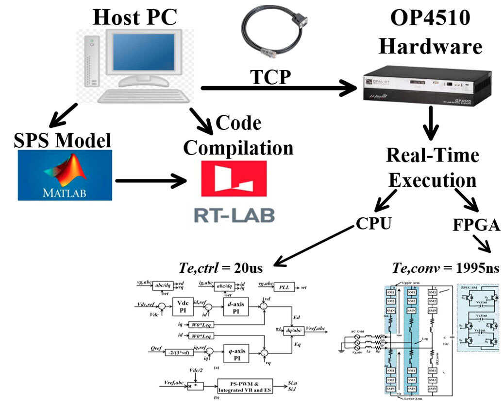
Figure 4: Real-time simulation platform architecture combining CPU and FPGA execution
Performance Under Real Grid Conditions
The proposed STATCOM was tested under realistic operating scenarios, including:
- Sudden changes in reactive power demand
- Transitions between capacitive and inductive compensation
- Variations in DC voltage levels
The results show that the system:
- Maintains perfectly sinusoidal grid currents
- Generates clean 17-level voltage waveforms
- Maintains the balance of internal capacitor voltages
- Responds promptly to dynamic grid conditions
These outcomes confirm that high performance can be achieved with significantly fewer components.
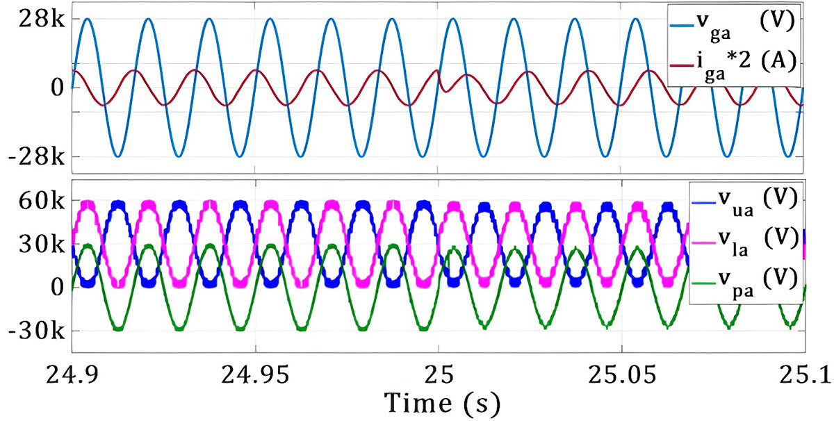
Figure 5: Grid voltage and current showing reactive power compensation
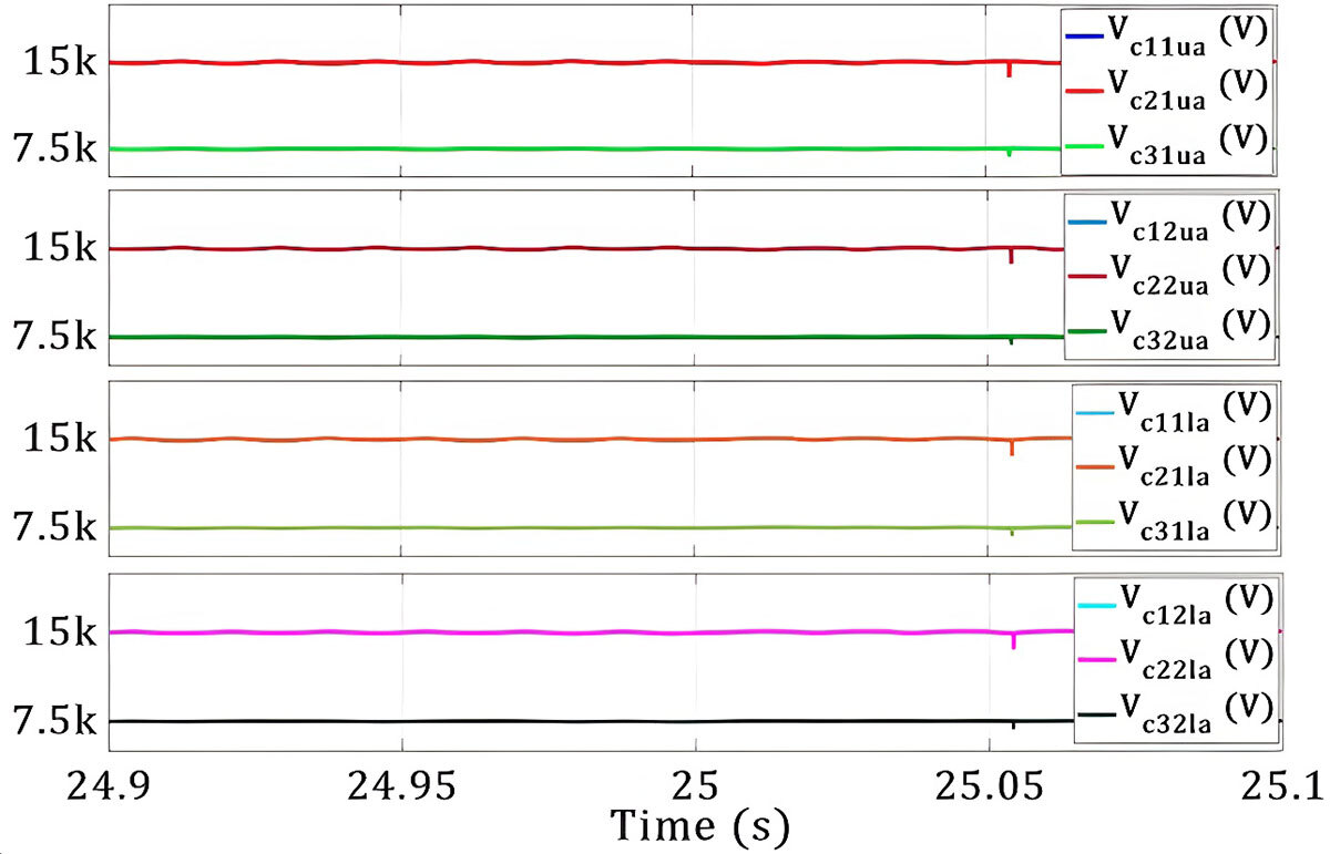
Figure 6: Internal capacitor voltage balancing during operation
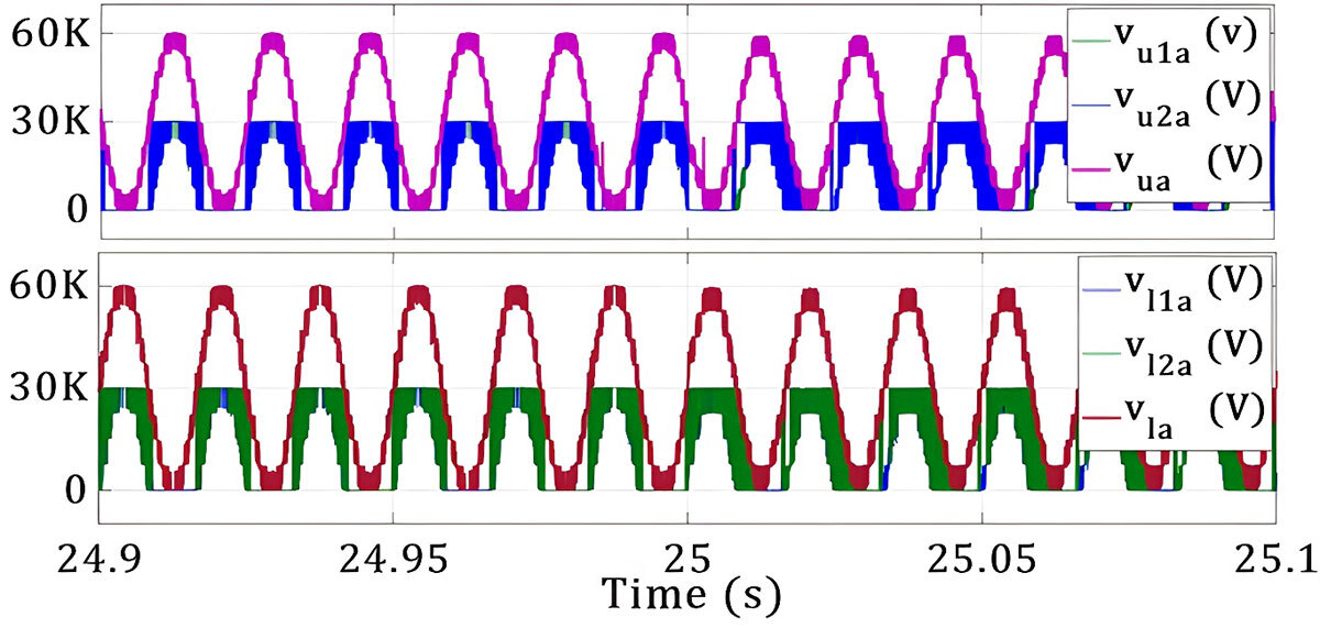
Figure 7: 17L- Phase voltages in each of the upper and lower arm of phase a
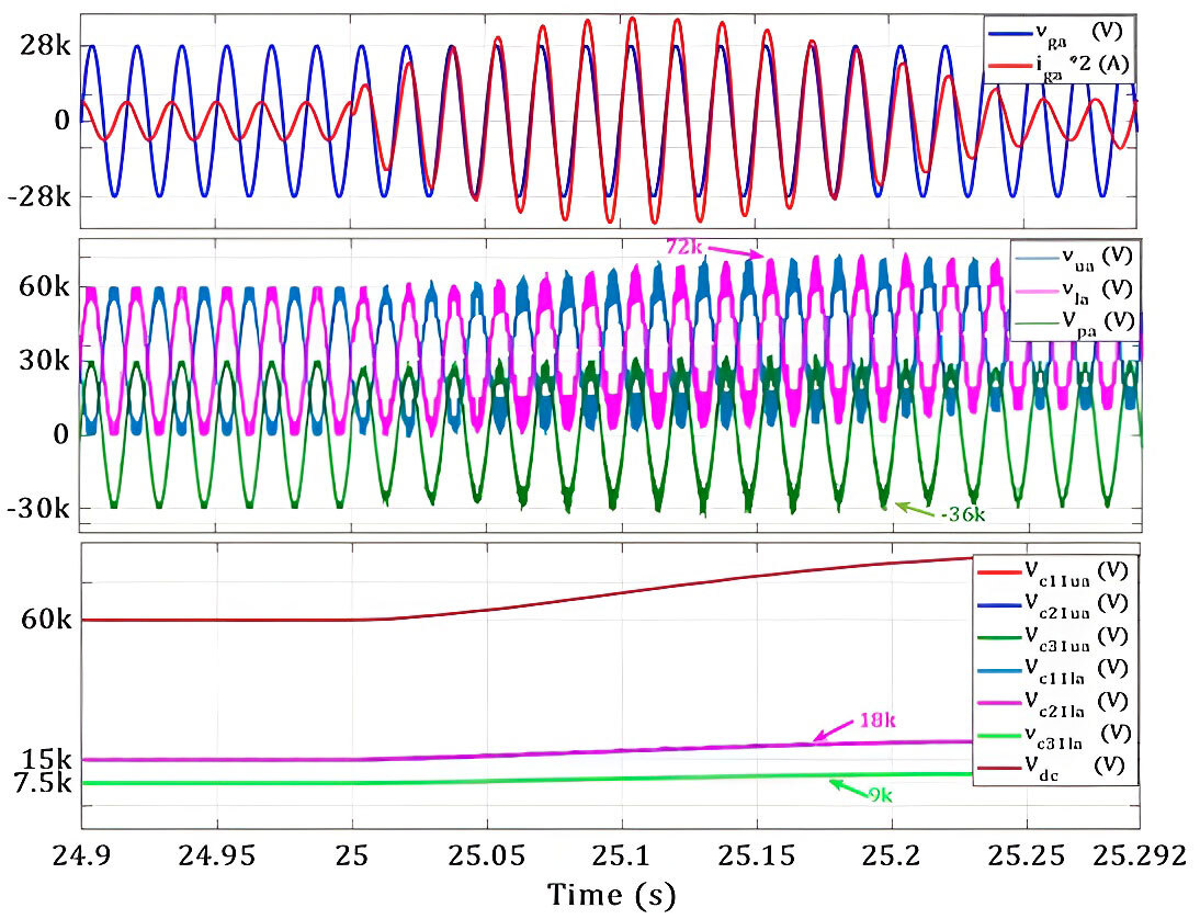
Figure 8: Dynamic operation: DC voltage variation
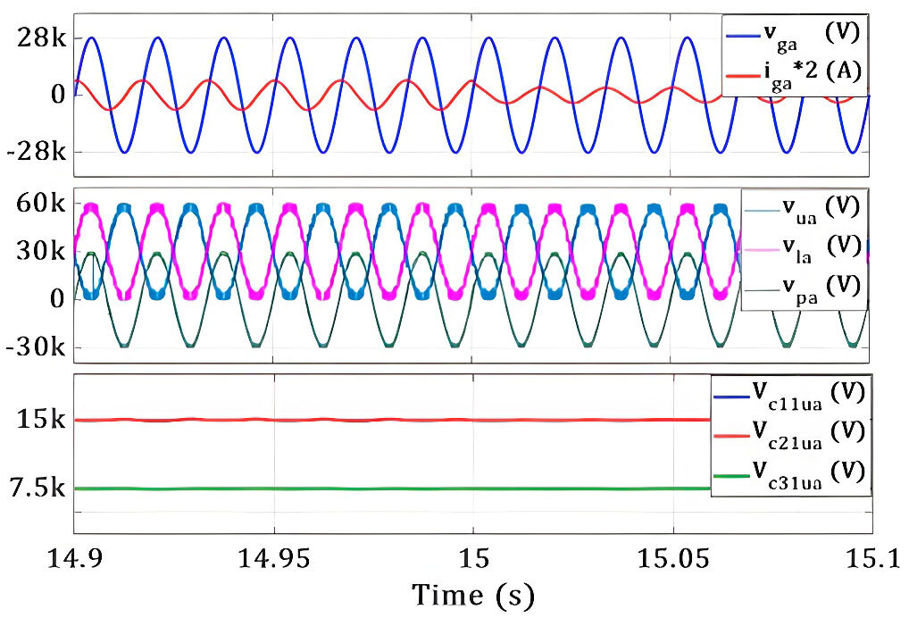
Figure 9: Dynamic operation: Capacitive reactive power reference -150 Mvar to -75 Mvar
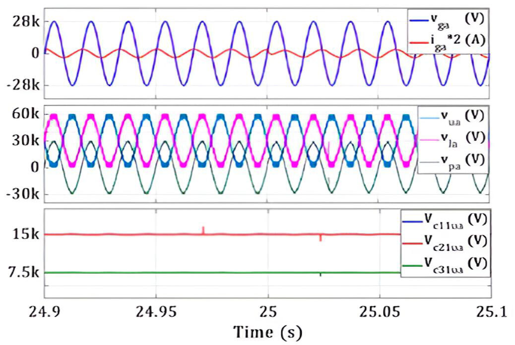
Figure 10: Dynamic operation: Capacitive to inductive reactive power reference -75 Mvar to +75 Mvar
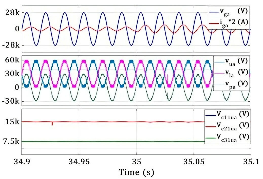
Figure 11: Dynamic operation: Inductive reactive power reference +75 Mvar to +150 Mvar
Practical Impact for Future Power Systems
This research demonstrates a practical path toward smaller, lighter, and more economical STATCOMs. By reducing the number of required submodules while maintaining excellent power quality, the proposed ZPUC-based MMC design offers clear advantages for:
- Medium-voltage distribution grids
- Industrial power quality solutions
- Future smart grid applications
Beyond STATCOMs, the same approach can be extended to other grid-connected converters, where efficiency, cost, and reliability are critical.
Looking Ahead
While the proposed topology shows strong performance, future work will focus on enhancing fault-handling capability and optimizing current control strategies. Combining the ZPUC concept with fault-tolerant designs could make it suitable for an even broader range of grid applications.
Additional Information
For more information on this research, please refer to the following research paper: S. Atanalian, F. Sebaaly, R. Zgheib and K. Al-Haddad, "Z Packed U-Cell Modular Multilevel Converter for STATCOM Applications," in IEEE Access, vol. 13, pp. 78795-78807, 2025, doi: 10.1109/ACCESS.2025.3566015.