Morphing Application to the UAS-S45 Drone for Aerodynamic Performance
Used with the permission of Hydra Technologies
Unmanned Aerial Vehicles (UAVs) need to achieve their optimal aerodynamic performance (maximum lift-to-drag ratio) for an extended range of flight conditions due to their broad flight envelope. The use of high-lifting devices in UAVs will broaden their flight envelope and extend their endurance. To address such challenges, the LARCASE team is investigating the development of continuous high-lift devices using the Morphing Wing Technology and accurate aerodynamic optimization modelling for the UAS-S45. The aim of this research is to design and further develop the best possible morphing airfoil shapes while minimizing drag and maximizing the endurance of UAS-S45. Using different optimization algorithms and efficient solvers, the LARCASE team managed to obtain an airfoil that increased the lift-to-drag ratio of the UAS-S45, and therefore showed increased aerodynamic efficiency in the UAS-S45. Keywords: Airfoil, Morphing, Leading Edge and Trailing Edge Optimization, Parameterization, Particle Swarm Algorithm, UAS-S45
Advanced Morphing Technologies
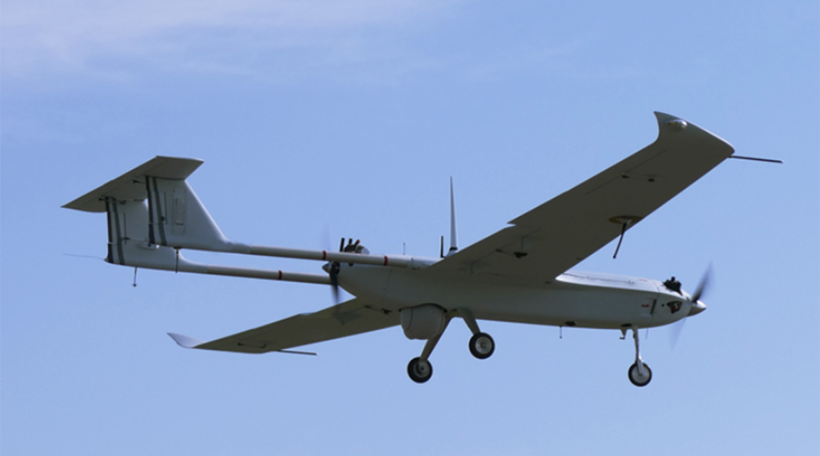
The goal of reducing global fuel consumption and its-related emissions has placed tremendous pressure on the aviation industry [1]. Reducing fuel consumption will benefit both global environment and the air transportation industry. According to the Air Transport Action Group (ATAG), a reduction in fuel burning will have a significant impact on the air transportation industry because the largest operating cost of this industry is fuel [1]. Highly committed researchers at our Research Laboratory in Active Controls, Avionics and AeroServoElasticity (LARCASE) are working on possible methods to reduce aircraft fuel consumption [2-9]. Morphing Wing Technology shows high potential in decreasing aircraft fuel consumption. Figure 1 shows the UAS-S45. Several morphing configurations that can provide better aerodynamic performance of the UAS-S45 with respect to its classical configurations are shown in Figure 1.
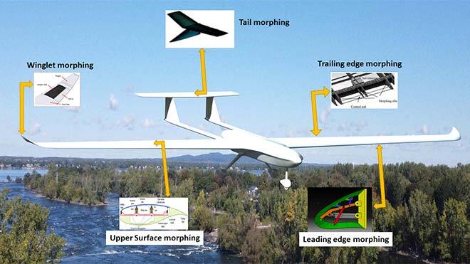
Figure 1- UAS-S45 with Potential Morphing Configuration Capabilities
Advanced Morphing Technologies are currently being studied worldwide. For example, the “Active Flexible Wing program” and the “Mission Adaptive Wing program from NASA” [10,11], a European Union initiative called “the New Aircraft Concepts Research” (NACRE) project, and “the Smart Intelligent Aircraft Structures” (SARISTU) [12] [13] funded within the Clean-Sky program are among several recent well-known research projects and programs.
In Canada, significant contributions in the field of morphing aircraft include projects such as the the “Mission Optimized Smart Structures” (MOSS) at the National Research Council of Canada [16]. Also noteworthy were the two projects funded by the CRIAQ: the CRIAQ 7.1 project called “Laminar Flow Improvement on an Aeroelastic Research Wing” at LARCASE, and the “Morphing Architectures and Related Technologies for Wing Efficiency Improvement—CRIAQ MDO 505”, a continuing part of the above-mentioned CRIAQ 7.1 project [14,15]. The achievements of the international Canadian-Italian CRIAQ MODO 505 projects are mentioned in various LARCASE publications [17,18]. The control laws for morphing wings using electrical actuators were designed, and experimental validation was done at the LARCASE Price-Païdoussis and IAR-NRC Wind Tunnels [19-22].
The purpose of this morphing wing optimization project is to obtain an aerodynamically efficient airfoil shape using the Droop Nose Leading Edge (DNLE) and Morphing Trailing Edge (MTE) technologies for the UAS-S45. The morphing wing project outcome demonstrated the capacity of simultaneous variation in specific parameters of its airfoil to improve the UAS-S45 aerodynamic performance.
Methodology to Obtain Aerodynamic Coefficients
This research was conducted at the LARCASE using the methodology described in Figure 2. Based on the aerodynamic optimization model, two cost objective functions were integrated with a geometrical shape parameterization model. The two cost objective functions were “drag minimization” and “endurance maximization”, respectively. An aerodynamic flow solver, XFoil and the Particle Swarm Optimization (PSO) algorithm were used to perform the aerodynamic optimization of the Morphing Trailing Edge (MTE) and Droop Nose Leading Edge (DNLE) airfoils for the UAS-S45 at different flight conditions chosen from manufacturer specifications.
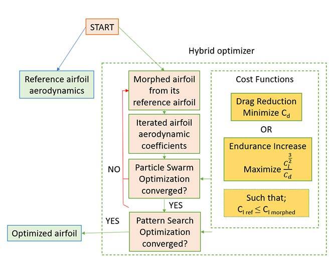
Figure 2- Optimization Procedure Steps
Low fidelity flow solvers such as XFoil can perform fast computations and produce highly accurate aerodynamic coefficients. However, optimization using a high-fidelity CFD model is often impractical due to its high computational cost. Fortunately, low fidelity models (e.g. Xfoil) can still provide excellent accuracy for the optimization process. Design challenges and morphing features further increase the complexity of the optimization process, as shown in Figure 3.
Two different aerodynamic solvers were used to calculate the aerodynamic coefficients: XFoil, and Reynolds-Averaged Navier–Stokes’s equations (RANS) solvers. The XFoil code and RANS are very well known for their good execution speed and results accuracy, and were used in this paper for the airfoil analysis in order to keep computational costs down. Lastly, the ANSYS Fluent solver was used to obtain high accuracy results by taking into account viscous boundary layers and flow separation phenomenon. Results were expressed in terms of aerodynamic coefficients.
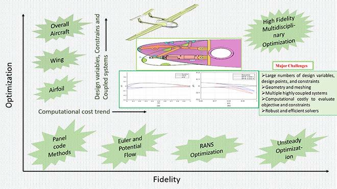
Figure 3- Design challenges for high-fidelity optimization analysis
Droop Nose Leading Edge (DNLE) Results
Optimization results have shown an increase in the CL versus CD for DNLE airfoils, as indicated in Figure 4(a). An increase of the lift coefficient was produced for the DNLE airfoils with respect to the baseline airfoil lift coefficient of up to 21%. Similarly, the aerodynamic performance showed a significant increase for the MTE configurations in the CL versus CD variation, as indicated in Figure 4(b).
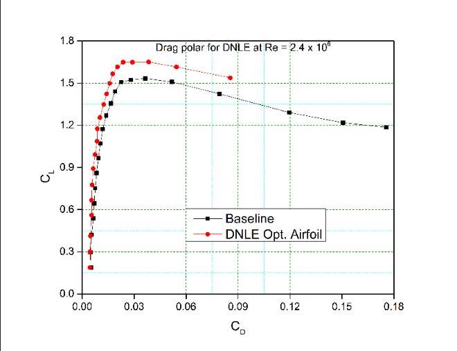
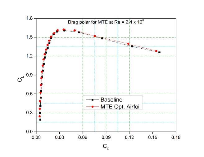
Figure 4- Aerodynamic performance in terms of CL versus CD for the (a) baseline vs. DNLE optimized airfoil and (b) baseline vs. MTE optimized airfoil
Figure 5(a) shows that the optimization process led to an increase in aerodynamic endurance, characterized by CL3/2/CD in the optimized DNLE airfoil, from 117 to 132 with respect to the CL3/2/CD of the baseline airfoil. An increase of the maximum lift coefficient of up to 8.13%, and of the efficiency of CL3/2/CD by 10.25% is shown in Figure 5(b). This result indicates an increased endurance performance for the MTE airfoil of the UAS-S45 with respect to its baseline airfoil.
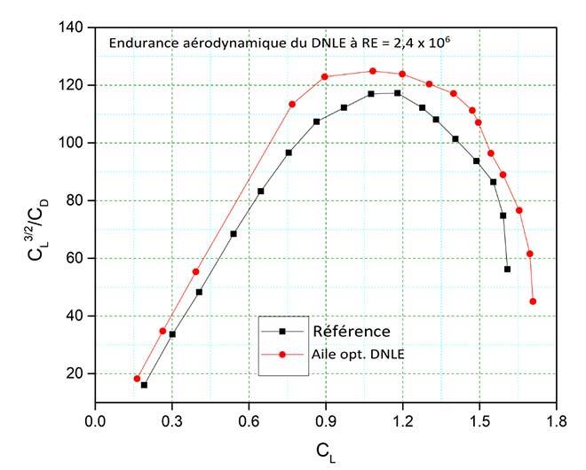
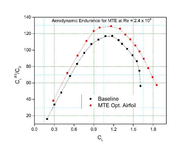
Figure 5- Endurance comparison for (a) baseline and DNLE airfoils, and (b) baseline and MTE airfoils
The pressure coefficients variations with the chord as the baseline and DNLE airfoils for an angle of attack of 4° are shown in Figure 6(a), and the pressure coefficients variations with the chord as the baseline and MTE are shown in Figure 6(b). The major changes in the DNLE airfoil pressure take place near the leading edge at its upper surface. The pressure peaks stay smooth on the remaining part of the airfoil. The MTE airfoil results lead to a significant change in pressure values at the trailing edge surface, as shown in Figure 6(b).
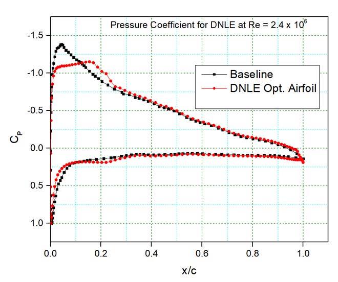
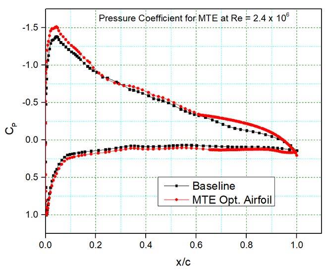
Figure 6- Pressure coefficients variations with the airfoil chord as a baseline versus optimized airfoils at the angle of attack of 4°
The DNLE airfoil shows higher gradients in comparison with those of the baseline airfoil. It is found that the leading edge propagates the energy towards airfoil downstream, thus a considerable decrease of turbulent kinetic energy (TKE) is observed in the wake turbulence. Velocity magnitudes of optimized airfoils at two different angles of attack, 4o and 10o, are shown in Figures 7(a) and 7(b), respectively. The Turbulent Kinetic Energy (TKE) occurring in the baseline airfoil, which starts at its upper surface, and moves towards its trailing edge is not observed in the DNLE optimized airfoil at an angle of attack of 4°, as seen in Figure 7(c). Figure 7(d) shows TKE occurring at an angle of attack of 10o.
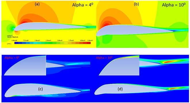
Figure 7- Velocity Magnitude and Turbulent Kinetic Energy Contour Plots for DNLE airfoil
Conclusion
So far, results obtained by the LARCASE team are encouraging. More study is being carried out using other novel optimization algorithms to further improve the aerodynamic efficiency of morphing wings. UAS-S45 landing, and take-off maneuvers and gust response studies will be included.
Acknowledgments
Our special thanks go to the Natural Sciences and Engineering Research Council of Canada (NSERC) for the Canada Research Chair Tier 1 in Aircraft Modeling and Simulation Technologies funding. The UAS-S45 data and UAS-S4 were obtained thanks to Hydra Technologies team members Mr. Carlos Ruiz, Mr. Eduardo Yakin and Mr. Alvaro Gutierrez Prado in Mexico, Mr. Oscar Carranza Moyao from LARCASE, and the Canadian and Quebec government organizations: Canada Foundation for Innovation and Ministère de l’Économie et Innovation. We would like to thank Mrs. Odette Lacasse for her support at ETS. And we would like to thank the NSERC and Prof. Jeremy Laliberte for their support within the CREATE-UTILI program.
Additional Information
For more information on this research, please refer to the following research paper:
Aerodynamic Design Optimization of a Morphing Leading Edge and Trailing Edge Airfoil–Application on the UAS-S45
Musavir Bashir, Simon Longtin-Martel, Ruxandra Mihaela Botez and Tony Wong
Special Issue Aircraft Modeling and Simulation Applied Sciences 11.4 (2021): 1664.