Analyzing a New Morphing Trailing Edge System
Purchased on Istock.com. Copyright.
This article presents a new trailing edge morphing system created by the LARCASE team. The proposed approach was to produce a deformation of the trailing edge using flexible wing ribs with slits. This system has the added benefit of being lightweight and easy to manufacture. Its functionality was validated through wind tunnel testing. When compared to a conventional aileron, the new system showed less wing drag and lower aircraft engine fuel consumption.
Introduction
The idea behind the morphing wing is to influence aircraft behaviour and performance by deforming the actual wing instead of using movable wing sections as in existing aircraft. The movable parts on a conventional wing are ailerons, flaps, spoilers, and slats.
In this research, we focused on replacing ailerons with a wing morphing system. Specifically, it is a deformation system for the wing’s trailing edge. Replacing ailerons with a wing morphing system has the added benefit of reducing wing air resistance and, ultimately, aircraft fuel consumption.
To be useful on an aircraft, the system must meet three key criteria:
- It must allow for improved wing performance.
- It must not increase wing mass.
- It must not increase total aircraft energy consumption.
Designing the Morphing Wing System
Since there were no constraints for the wing structure (unlike some previous LARCASE wing morphing projects [1] [2] [3] [4]), we chose a skeleton-like wing structure, composed of a main spar—to support the weight of the aircraft in the air—and ribs, to give the wing its aerodynamic shape.
To produce a deformation of the wing’s trailing edge, we made the ribs flexible at their trailing edge. Modifying the shape of the rib allowed us to modify the aerodynamic shape of the wing. To obtain a flexible rib, slits were made leaving only a thin layer in the centre [5]. Figure 1 shows the central rib of the morphing trailing edge system, called MTE for “Morphing Trailing Edge”. Using a morphing wing system, we were able to obtain a smooth-looking modification of the wing shape, as opposed to using an aileron, as shown in Figure 2. We chose to divide the slits into three regularly spaced pairs between the centre and the trailing edge of the rib to produce the smooth deformed shape.
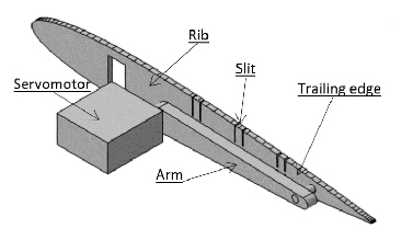
Figure 1 MTE deformation control

Figure 2a NACA0012 profile with inclined aileron

Figure 2b NACA0012 profile with deformed MTE
Manufacturing and Wind Tunnel Testing
To validate the operation of the MTE, our model was tested in the LARCASE Price–Païdoussis wind tunnel (Figure 3) [6] [7] [8] [9]. To determine if the MTE prototype helped improve the wing’s aerodynamic performance, we carried out comparative tests using a wing model equipped with an aileron; the models of both systems (MTE and aileron) had the same measurements for more accurate comparisons. Since we used an aileron model from a previous study [10], we designed the MTE (Figure 4) model with the same measurements (Figure 5). Using an aerodynamic balance designed by LARCASE students [11], we obtained the lift (wing lift ability) and drag (air resistance) forces of the wing models during the tests. This way, we could plot aerodynamic coefficient variation curves for the two systems (Figure 6 and Figure 7) from the measured forces and the geometric wing dimensions.
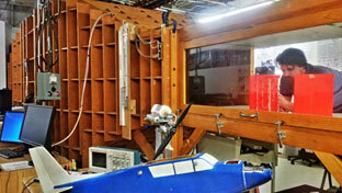
Figure 3 LARCASE Price–Païdoussis subsonic wind tunnel
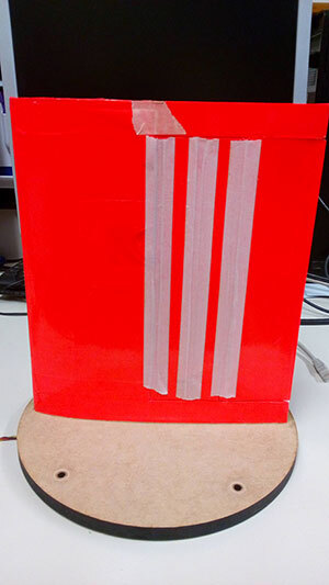
Figure 4 Model of the MTE-equipped wing
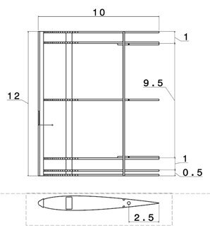
Figure 5 2D map of the aileron-wing model (shown in “inches”)
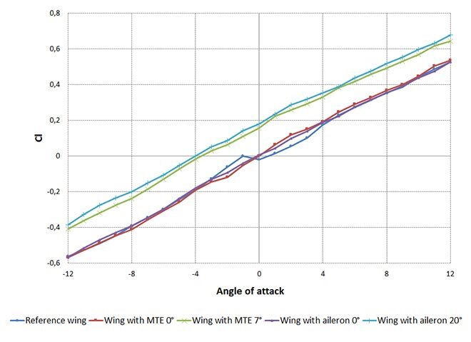
Figure 6 Variation of the lift coefficient according to the wing’s angle of attack
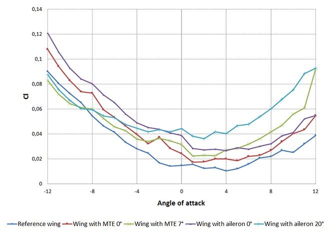
Figure 7 Variation of the drag coefficient according to the wing’s angle of attack
As shown in Figures 6 and 7, given the same variation in lift coefficients, the drag coefficient of the MTE wing is lower than in the wing with aileron. It can be concluded that the MTE improves wing performance compared to a conventional aileron. Therefore, our design meets the first criterion.
In order to meet the wing mass conservation requirement, we used the same structure for the MTE as that of the aileron (spar and ribs), and the same actuator (servomotor).
Finally, the third criterion required avoiding the consumption of more energy than the amount that was saved. To validate this point, we measured the energy consumption of the two systems during the wind tunnel tests. We obtained a constant consumption of 25.2 mW for the aileron control, 25.2 mW for the MTE control without deformation, and 504 mW with a 7° deformation of the MTE. The MTE consumes more energy than a conventional aileron because of the actuator’s role in rib deformation. However, because the MTE reduces wing drag, the engine’s energy requirement is reduced. Yet engine consumption is over hundreds of thousands times greater than that of an actuator. A 1% reduction in engine consumption saves several dozen watts of power, which is much higher than the extra consumption required by the MTE.
Conclusion
This analysis allowed us to demonstrate the functionality and efficiency of our morphing wing trailing edge prototype. In addition to being simple to manufacture, the MTE prototype has met the criteria for use on an aircraft. The next step will be to integrate the MTE into a small aircraft, such as the LARCASE UAS-S45, to validate flight behaviour.
Additional Information
For more information on this research, please refer to the following paper:
Communier, David; Botez, Ruxandra; Wong, Tony. 2019. “Experimental Validation of a New Morphing Trailing Edge System using Price–Païdoussis Wind Tunel Tests.” Chinese Journal of Aeronautics, 32(6): 1353–1366.


