Rethinking the Ultrasonic Inspection of Aircraft Engine Forgings

Disk forging. @ Jorge Rodrigues
Our research in partnership with aerospace engine manufacturer brought a new perspective into manufacturing fan disk forgings. Even though consolidated, this process carries the burden of an extra machining step that is prohibitively expensive. We investigated and developed innovative ultrasonic testing methods to evaluate the possibility of avoiding this step, thus reducing the environmental footprint of the entire process. Keywords: Ultrasonic testing, aerospace, phased array ultrasonic imaging.
An Expensive Intermediate Step
Ultrasonic inspection is a critical process in the aerospace industry, especially for aircraft fan disk forgings. Since these parts are bulky, the only way to ensure their integrity is by “looking” inside them using ultrasonic waves. As it is done for health reasons—when a physician searches for abnormal tissue during an exam—inspectors search for cracks or inclusions that may cause failures within the material’s microstructure.
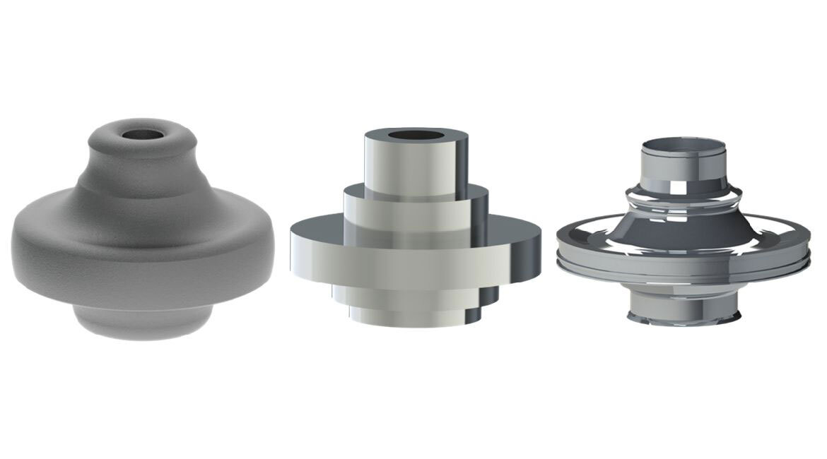
Until now, the process consisted of the steps shown in the infographic below. Essentially, the as-forged shape is too complex and difficult to inspect using current techniques. The solution was an intermediate machining of the forging, producing a sonic geometry. This shape greatly eases ultrasound transmission but at a high cost. Indeed, the material of these disk forgings is an expensive and hard Ni-alloy, which raises the challenge and costs of machining this material. Also, all the resources spent to reach the ultrasonic inspection are wasted when flaws are found. Thus, avoiding sonic machining would represent a significant step toward reducing the environmental footprint of the entire process. The big question is: Is it feasible to inspect the as-forged shape ultrasonically?
Phased Array Ultrasonic Testing
Obviously, a novel approach was required to enable ultrasonic inspection directly on the as-forged shape. Our research found this solution with the phased array ultrasonic testing (PAUT). Essentially, these arrays make it possible to convert sound echoes into sharp images of the components’ interior through advanced reconstruction algorithms like the total focusing method (TFM). Piezoelectric elements in the probe transmit and receive ultrasonic waves into and from the part. In post-processing, the algorithm maps the pathways of each wave and converts them into position-amplitude pair information. This is done for all elements in the array so that the data can be superposed through summation. This process reinforces redundant information from reflectors, while eliminating random echoes. It generates sharp images of the component’s cross-section with features such as material edges and internal defects presented as indications.
Optimizing Probe Position
However, this could not be as easy as simply applying PAUT to our case. Our first findings showed that the curved interfaces acted as lenses, distorting the images depending on the interface shape, material, and sensor properties. To mitigate this effect and ensure the best image, we developed an algorithm that predicts the performance and indicates the optimal probe position. Our findings show that it is possible to see the effect of the probe position on the image quality, as per the image below. The three internal defects are only visible if the probe position is optimized.
This first step allowed us to go even further, by developing a novel method to generate images of the specimen’s complex interior. To do so, we combined the powerful TFM with robotization and a digital twin that optimizes the probe position, ensuring the best scanning. This method was named global TFM or gTFM. Essentially, the robot controls and places the probe in an optimized path to scan all around the part. Then, the images from all directions are composed into a single global image that depicts the entire cross-section of the specimen. And to prove this concept, our method was applied to inspect an aerospace forging mock-up with a complex geometry and thirty artificial internal defects. We chose this extreme scenario to challenge the validity and limits of our method. The infographic below depicts the experimental setup and our main finding. Below, there is also a video illustrating the inspection in action and the image-forming process.
Results show a sharp image of the entire cross-section of the part. Here, it is possible to see all internal defects highlighted with high-amplitude indications. Such a high contrast image and the depiction of the entire profile of the part facilitate the operator’s interpretation. All in all, this finding confirmed the method’s capability of inspecting complex specimens.
Ultrasound Inspection for As-Forged Components
Based on our findings, we strongly believe that inspecting as-forged components ultrasonically is feasible. However, we must keep in mind that the aerospace sector is pragmatic when it comes to changing standards that have been around for years. A long journey of in-depth investigation still lies ahead, as sensitivities to different flaws and calibration methods must be studied. Yet, this research introduces a new idea and a proof of concept that will hopefully be a stepping stone to broad industrial deployment, changing how aerospace engine forgings are manufactured.
Additional Information
For more information on this research, please read the following research paper:
Mansur Rodrigues Filho, J.F.; Bélanger, P. Probe Standoff Optimization Method for Phased Array Ultrasonic TFM Imaging of Curved Parts. Sensors 2021, 21, 6665.


