October 20, 2025
Abstract
This research presents a novel concept of twisted-morphing ailerons for the UAS-S45 platform. Unlike conventional hinged surfaces, the proposed ailerons achieve roll control by smoothly twisting along their span, which enhances maneuverability and minimizes drag. High-fidelity aerodynamic optimization was applied to evaluate each aileron independently. The findings indicate that the twisted morphing ailerons can improve their rolling effectiveness by 34% while reducing induced drag by 61% compared to standard ailerons designs. These outcomes highlight the strong potential of twist-morphing technology to significantly advance both flight efficiency and control capabilities.
Keywords: rolling efficiency, aileron performance, induced drag, twisted morphing aileron
A Bio-Inspired Twisted Morphing Wingtip
Over the past decades, investigations into morphing wing concepts have advanced, with many projects moving beyond the conceptual stage to focus on the practical aspects of manufacturing, integration, and design. Because the manufacturing represents the final and most critical step, careful attention must be directed toward transitioning these morphing designs into a real aircraft.
Conducting aerodynamic simulations is typically the first essential step in verifying the benefits of a morphing wing concept. Studies have shown that prototypes which have reached the manufacturing stage have successfully demonstrated their effectiveness. Over the years, a wide variety of morphing wing configurations have been proposed, each of them was tailored to meet different flight requirements and maneuvering capabilities observed also in nature. Examples include span-extension or telescopic wings [1-3], drooped leading edges [4-6] variable sweep designs [7], upper surface morphing [8-11], variable thickness profiles [12], and variable camber mechanisms [13, 14]. Among them, camber morphing systems—particularly Morphing Trailing Edge (MTE) concepts [15-17]—have received greater attention because of their strong potential to improve aerodynamic efficiency.
The objective of this study is to identify a morphing wing concept capable of improving rolling performance while simultaneously decreasing downwash and induced drag. From an aerodynamic perspective, the components most directly linked to this goal are the ailerons. However, the key challenge lies in determining the most effective morphing strategy to apply on the ailerons.
Roll Motion
In order to execute a rolling maneuver, the aircraft relies on asymmetric deflections of the ailerons on each wing. When an aileron deflects downward, it increases the lift on that wingtip, while the opposite upward deflection lowers the lift on the other side of the wingtip, sometimes provoking the wing to stall. The imbalance in lift distribution across the span generates a rolling moment along the wing longitudinal axis. This imbalance causes the aircraft to rotate either clockwise (positive roll) or counterclockwise (negative roll), depending on the relative positions and displacements of the left and right ailerons. For example, if the right aileron moves upward while the left one moves downward, the aircraft experiences a positive roll, and the reverse configuration induces a negative roll. Figure 1 depicts the UAS-S45 performing such a rolling motion.
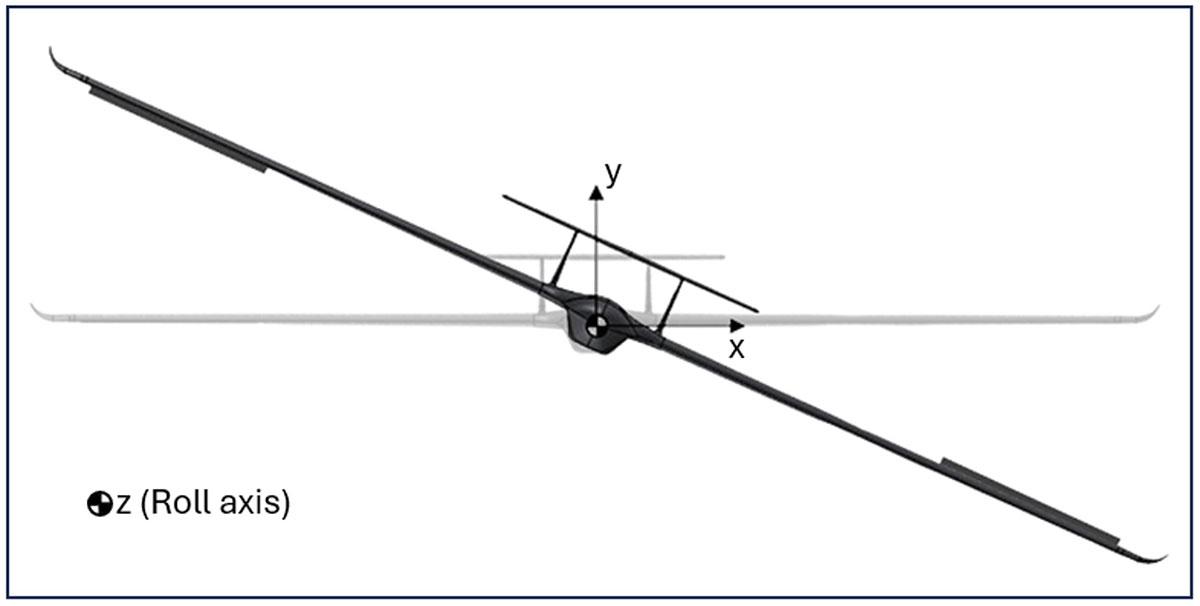
Fig.1 Schematics of an UAS-S45 in a rolling maneuver
Traditionally, aircraft have relied on their hinged ailerons to generate roll, meaning that roll effectiveness has always been closely related to their performance. In some cases, such as business jets, spoilers are also employed to initiate roll due to their faster actuation relative to ailerons. Inspired by birds, who achieve roll by twisting their wingtips, a similar approach can be applied to aircraft by replacing discrete deflections with a smooth twist deformation at wingtips. Morphing technology provides the means to apply this concept. By applying continuous twist instead of abrupt aileron or spoiler deflections, rolling efficiency can be enhanced. In this study, a novel twisted-morphing aileron design is proposed to obtain this type of roll control. The UAS-S45 is selected as the reference platform, and its performance with conventional hinged ailerons is compared with their proposed morphing configuration.
Optimization Setup
The main goal of this work is to optimize the twiste-morphing aileron design in order to enhanced its rolling performance. The optimization strategy relies on manipulating the lift generated on the wingtips: one wing is adjusted to maximize the lift, while the opposite wing is configured to minimize it. This imbalance in spanwise lift distribution produces the rolling moment required for maneuvering. The overall optimization framework adopted in this research is illustrated in Figure 2.
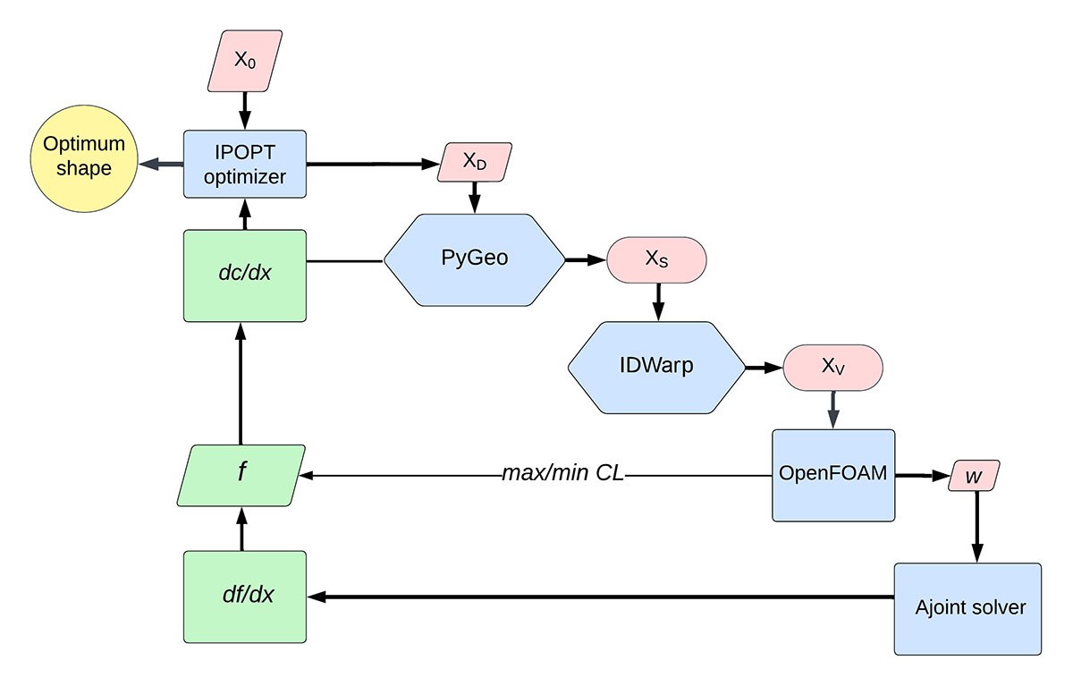
Fig. 2 DAFoam optimization process for twist morphing aileron, X0: initial variables, XD: design variables, XS: surface coordinates, XV: volume mesh, w: state variables, f: objective function
The optimization is carried out under cruise conditions for the UAS-S45, with a flight speed of 70 knots (28.3 m/s), an initial angle of attack of 0, and an altitude of 15,000 ft.
Morphing Ailerons
After completing the optimization for both wings, their new configurations are integrated into the fuselage to assess the UAS-S45’s rolling performance. During this stage, simulations are carried out in OpenFOAM using a refined mesh, particularly concentrated near the wingtips, to capture detailed flow behavior around the morphing ailerons. Figure 3 shows the static pressure contours on the upper and lower surfaces of the UAS-S45.
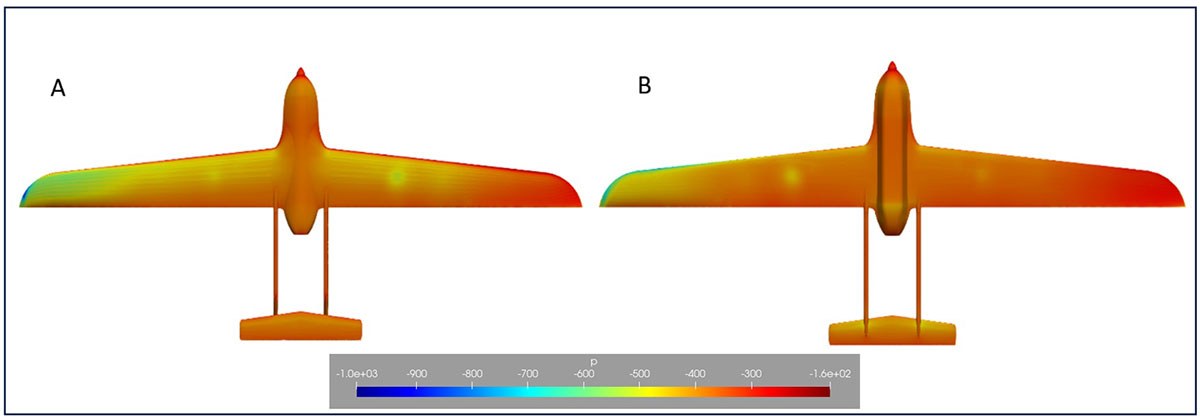
Fig 3. Static pressure contours on the A) upper and B) bottom surface of an UAS-S45
The static pressure contours in Figure 3 reveal a clear asymmetry between the left and right wingtips. The downward twist on the left wing (Fig. 3-B) generates higher pressure on its lower surface, while the upward twist on the right wing (Fig. 3-A) increases the pressure on its upper surface. A key benefit of using morphing ailerons is the smooth distribution of pressure across both the chordwise and spanwise directions, avoiding abrupt pressure peaks at the transition between the rigid and the twisted sections.
The flow around the twisted ailerons is illustrated using velocity streamlines, as shown in Figure 4. These visualizations capture in detail the airflow recirculation and its variation in velocity magnitude.
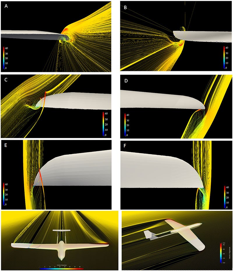
Fig. 4 Velocity streamlines around morphing twisted ailerons from different views. A) Downward twist-front view, B) Upward twisted front view, C) Downward twisted-isometric view, D) Upward twisted-isometric view, E) Downward twisted top view, F) Upward twisted top view, G, H) UAS-S45 equipped with morphing ailerons
Figures 4-B, 4-D, and 4-F present the upward-twisted morphing aileron from corresponding perspectives. Figures 4-G and 4-H depict the UAS-S45 fitted with the morphing ailerons. These figurers demonstrate that the aircraft’s rolling motion is driven entirely by the opposite flow patterns. On a downward-twisted aileron, the airflow is concentrated mainly over the upper wingtip surface, while on an upward-twisted aileron, the flow occurs on the lower surface. This reversed flow distribution induces a corresponding asymmetry in pressure, producing uneven lift and generating the roll moment.
Figures 4-C and 4-D highlight the flow recirculation for both morphing ailerons. For the downward-twisted aileron, the recirculation appears on the upper surface, while for the upward-twisted aileron, it is present on the lower surface. The circular shape of the wingtips confines this recirculation to a limited region, with its intensity diminishing immediately past the wingtip. Furthermore, the smooth transition between the rigid and morphing sections prevents the onset of turbulence at the start of the twist, as shown in Figures 4-G and 4-H.
Comparison between Hinged and Morphing Ailerons
This section presents a comparison between hinged and twisted-morphing ailerons in terms of rolling moments and overall aerodynamic performance. As discussed previously, analyzing rolling moments allows the assessment of aileron effectiveness in terms of both roll rate and control authority. Table 1 summarizes the roll moments for both aileron types.
Table 1 Comparison of the UAS-S45 with hinged and twisted morphing ailerons
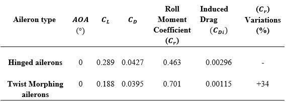
Figure 5 displays the static pressure distribution for the UAS equipped with hinged ailerons. The sharp discontinuities at the aileron gaps highlight areas of peak pressure. These abrupt pressure changes also contribute to wingtip-induced drag, as they promote an interaction between high-pressure flow beneath the wing and low-pressure flow above, generating additional vortices in addition to the standard wingtip vortices.
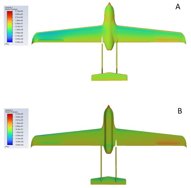
Fig. 5 Static pressure contour for the UAS-S45 with hinged ailerons: A) upper surface, B) lower surface
Conclusion
This work highlights one key advantage of the morphing wing technology. This study focuses on twist morphing as the primary morphing strategy, successfully achieving the intended objectives. The approach was applied to the wingtip with the goal to enhance rolling maneuvers by replacing traditional hinged ailerons with twisted-morphing ailerons.
The results for the twisted-morphing ailerons showed a 34% increase in roll moment, which directly improved the control effectiveness and maneuverability, enabling faster roll rates compared to those of conventional hinged ailerons. In addition, the morphing ailerons reduced the induced drag by 61%, largely due to the elimination of gaps around the aileron surfaces.
Additional Information
For more information on this research, please read the following paper:
Negahban MH, Bashir M, Priolet C, Botez RM. Novel Twist Morphing Aileron and Winglet Design for UAS Control and Performance. Drones. 2024; 8(8):392. https://doi.org/10.3390/drones8080392
References
[1] Samuel J.B., Pines D. Design and testing of a pneumatic telescopic wing for unmanned aerial ……….vehicles. Journal of Aircraft 2007; 44(4):1088-99.
[2] Elelwi M., Botez R.M., Dao T-M. Structural sizing and topology optimization based on weight ………..minimization of a variable tapered span-morphing wing for aerodynamic performance ………..improvements.Biomimetics 2021; 6(4):55.
[3] Elelwi M., Pinto F.S., Botez R.M., Dao T-M. Multidisciplinary optimization for weight saving in a ……….variable tapered span-morphing wing using composite materials—Application to the UAS-S4. ……….Actuators. 2022; 121.
[4] Bashir M., Negahban M.H., Botez R.M., Wong T. Numerical Simulation of the Transient Flow ……….around the Combined Morphing Leading-Edge and Trailing-Edge Airfoil. Biomimetics 2024; ……….9(2):109.
[5] Bashir M, Longtin-Martel S, Botez RM, Wong T. Optimization and design of a flexible droop-nose ……….leading-edge morphing wing based on a novel black widow optimization algorithm—Part I. ……….Designs 2022; 6(1):10.
[6] Bashir M., Botez R.M., Wong T., Design and Optimization of Droop Nose Leading Edge (DNLE) ……….Morphing Wing Skin for the UAS-S45. AIAA SCITECH 2024 Forum. 2024; 2150.
[7] An J, Yan M, Zhou W, Sun X, Yan Z, Qiu C. Aircraft dynamic response to variable wing sweep ……….geometry. Journal of Aircraft 1988; 25(3):216-21.
[8] Koreanschi A., Sugar Gabor O., Acotto J., Optimization and Design of a Morphing Aircraft Wing ……….Tip Demonstrator at Low Speed for Drag Reduction, Part I–Aerodynamic Optimizations Using 3 ……….Algorithms: Genetic, Bee Colony and Gradient Descent. 2017.
[9] Botez R,M,, Koreanschi A,, Sugar Gabor O., Numerical and experimental transition results ……….evaluation for a morphing wing and aileron system. The Aeronautical Journal 2018; ……….122(1251):747-84.
[10] Popov A.V., Botez R.M., Labib M., Transition point detection from the surface pressure distribution ……….for controller design. Journal of Aircraft 2008; 45(1):23-8.
[11] Botez R.M., Molaret P., Laurendeau E., Laminar flow control on a research wing project ……….presentation covering a three year period. Canadian aeronautics and space institute annual general ……….meeting. 2007.
[12] Liu, Z., Dai N., Wang, H., Wu L., Design of Variable Thickness Wing Based on Two-way Shape ……….Memory Alloy Drive. 2021 2nd International Conference on Intelligent Design (ICID). 2021; 88-……….92.
[13] Xiasheng S., Jingfeng X., Jin Z., Zhigang W., Wenjuan W., Zhang M., Design and validation of a ……….variable camber wing structure. Chinese Journal of Aeronautics 2024; 37(2):1-11.
[14] Negahban M.H., Botez R.M., Razavi S.E., New method for the flow modeling around chord-wise ……….morphing airfoil. AIAA SCITECH 2022 Forum. 2022; 2574.
[15] Pecora R., Magnifico M., Amoroso F., Monaco E., Multi-parametric flutter analysis of a morphing ……….wing trailing edge. The Aeronautical Journal 2014; 118(1207):1063-78.
[16] Pecora R., Dimino I., Amoroso F., Ciminello M., Structural design of an adaptive wing trailing ……….edge for enhanced cruise performance. Proceedings of the 24th AIAA/AHS Adaptive Structures ……….Conference. 2016.
[17] Concilio A., Dimino I., Pecora R., Ciminello M., Structural design of an adaptive wing trailing ……….edge for enhanced cruise performance. 24th AIAA/AHS Adaptive Structures Conference. 2016; ……….1317.
[18] Barbarino S., Bilgen O., Ajaj R.M., Friswell M.I., Inman D.J., A review of morphing aircraft. ……….Journal of intelligent material systems and structures 2011; 22(9):823-77.
[19] Negahban M.H., Bashir M., Traisnel V., Botez R.M., Seamless morphing trailing edge flaps for ……….UAS-S45 using high-fidelity aerodynamic optimization. Chinese Journal of Aeronautics 2024; ……….37(2):12-29.
[20] Amendola G., Dimino I., Concilio A., Pecora R., Amoroso F., Actuation system design for a ……….morphing aileron. Applied Mechanics and Materials 2015; 798:582-8.
[21] Ameduri S., Dimino I., Concilio A., Mercurio U., Pellone L., Specific Modeling Issues on an ………Adaptive Winglet Skeleton. Applied Sciences 2021; 11(8):3565.