November 4, 2026
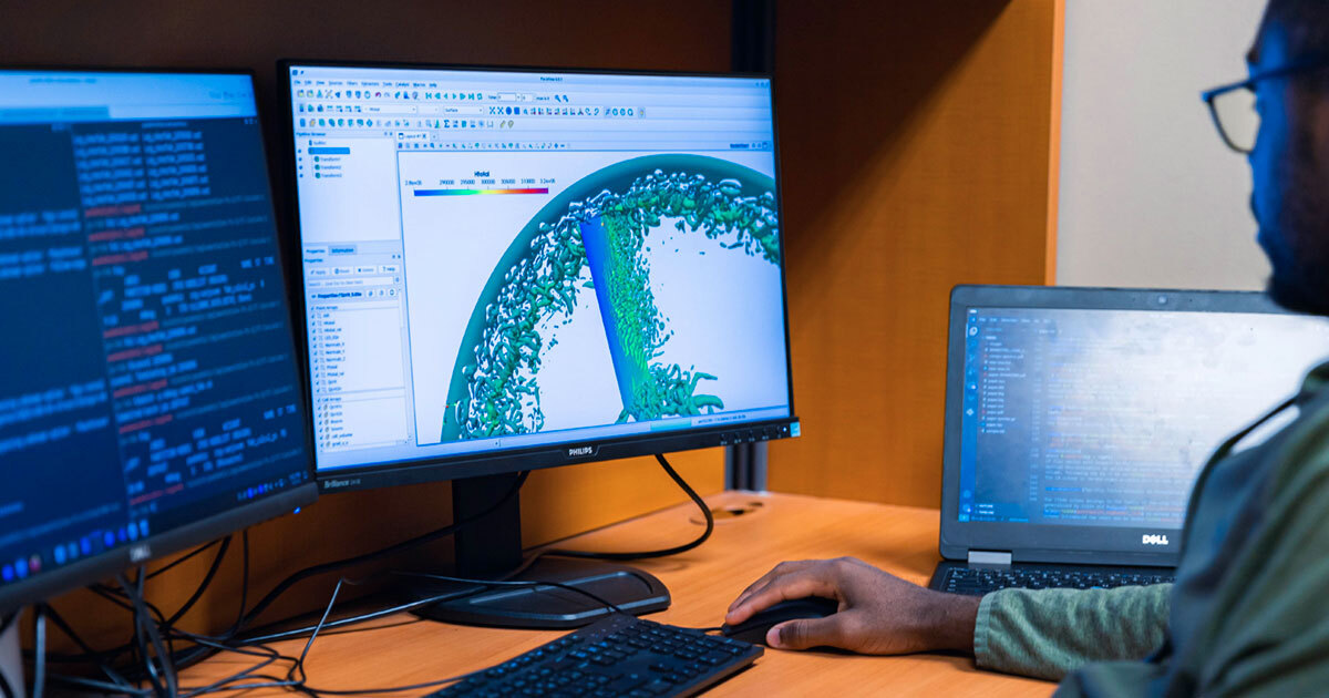
Figure 1: Visualization of turbulent structures around a propeller blade
The tail rotor: A source of noise pollution
The flexibility of helicopters in hard-to-reach areas, combined with their suitability for emergency missions such as medical evacuations, makes them essential modes of transportation for both vital public services and private individuals. Yet, the ever-increasing number of flights over urban areas means greater noise pollution for people living near flight paths, highlighting the need to design quieter aircraft. The acoustic spectrum of operating helicopters is dominated by noise from the main rotor. However, the tail rotor contributes significantly to the noise by generating components within the human ear’s sensitivity range, which can be highly disturbing.
As part of a continuous improvement initiative and the electrification of flight controls, Bell Textron Canada has developed a new tail rotor architecture for helicopters. It consists of four electrically driven propellers housed within a duct, as shown in Figure 2. With the duct, new sources of noise must be characterized to optimize design. This study focused initially on analyzing the noise sources associated with the rotating part of the system (the rotor), excluding the stationary part (the stator). The objective was to specifically identify and characterize the acoustic sources related to the rotor.
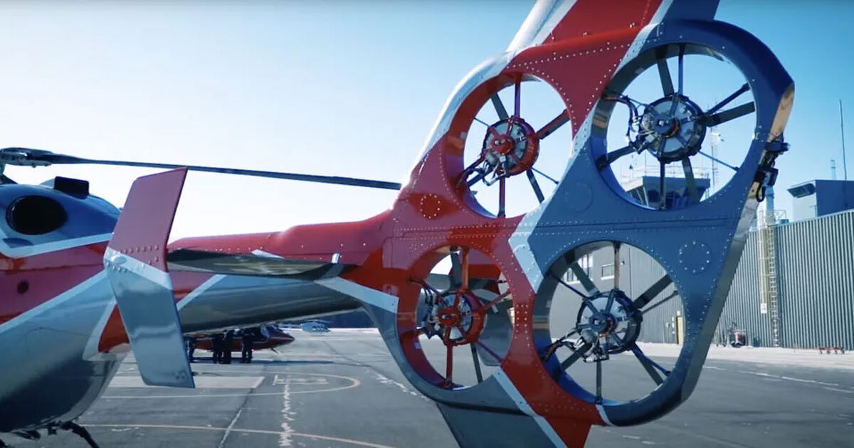
Figure 2: EDAT (Electrically Distributed Anti-Torque) tail rotor architecture
Numerical simulations for acoustics
In general, the airflow around propellers consists of air vortices of various sizes that fluctuate significantly over time, as shown in Figure 1.
The propeller blades’ rotational motion and their interaction with these structures generate pressure variations that propagate as sound waves. This noise consists of localized components at specific frequencies, called tonal components, and components spread over a wide range of frequencies, known as broadband components.
To estimate the noise produced by the rotor, our approach initially involved numerically solving the Navier-Stokes equations. These describe the time evolution of an air particle velocity and pressure within a computational domain surrounding the propeller. Including all vortices would be extremely computationally intensive. Therefore, only the largest ones were solved, while the others were modelled using subgrid-scale models.
Once the pressure at the propeller blade surface was determined, the noise level detected by a microphone placed 2 m from the propeller was calculated using an equation that depends on this surface pressure and other aerodynamic parameters. Unlike experimental methods, this approach not only estimates the noise generated but also identifies its root causes.
Blade-tip vortex: The main source of broadband noise
The results highlight two areas primarily responsible for the broadband noise generated by the propeller blades. The first is at the base near the hub and is associated with the low frequencies of the acoustic spectrum. The second is at the upper tip, near the duct. This area dominates the acoustic spectrum at higher frequencies – in the range where the human ear is most sensitive – with noise levels 5 to 10 dB higher than those emitted by the rest of the blade. Here, we observed a leakage flow and the formation of a tip vortex in the radial gap between the blade and the duct. These phenomena generate pressure variations in this area, which then propagate radially throughout the rest of the domain. A mode decomposition analysis highlights the predominant role of vortex oscillation in generating these pressure fluctuations.
Numerical data requiring validation
A comparison between the numerical results and the experimental data reveals good agreement with the generated thrust. From an acoustic standpoint, the predicted levels also agree well with the measurements at low frequencies. However, we observed an overestimation of around 5 to 10 dB at high frequencies, as shown in Figure 3.
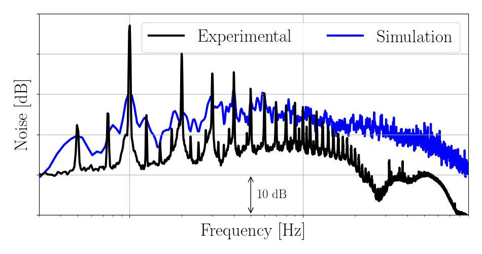
Figure 3: Noise (in dB) generated by the rotating part of a propeller in the EDAT configuration
These discrepancies likely stem from vortex resolution at the blade tip, possibly due to the numerical methods used. Further analysis will be needed to confirm this hypothesis.
Conclusions
Despite the differences observed in the experimental data, this study identified the tip area as the primary source of noise emitted by the moving blades of the EDAT tail rotor. The numerical analysis also helped refine the selection of certain numerical parameters and the convergence time required to obtain usable acoustic data. These results point to avenues for improvement both in future analyses and for the design of quieter rotors.
Additional Information
For more information on this research, please refer to the following article: Ralph Kinte Pouhe Hiol, Marlène Sanjosé, “Aerodynamic noise contributions in a ducted tail-rotor configuration using high-fidelity simulation,” International Journal of Heat and Fluid Flow, Volume 121, Part 2, 2026, 110518, ISSN 0142-727X.