November 10, 2025
Abstract
Industrial heat treatment fundamentally underpins reliable manufacturing. In tempering, large steel forgings must follow controlled thermal histories so that final mechanical properties meet specifications without requiring rework. Because furnace cycles are energy-intensive and strongly linked to metallurgical transformations, non-uniform temperatures inside the chamber can ripple outward, lengthening cycles, wasting energy, and most importantly, creating batch-to-batch variability. As plants become more electrified, a practical design question becomes decisive: where to install heating elements and what fraction of the wall surface to occupy. The study summarized here examines how heating elements placement and surface coverage in an industrial electric tempering furnace influence key thermal metrics of uniformity and identifies coverage bands that improve consistency both within blocks and across batches.
Keywords: Industrial electric furnace, heat treatment, temperature uniformity, optimization, heating element placement, CFD simulation.
Why Uniform Heating is Difficult
Uniform heating sounds simple, but scale and geometry make it difficult. In a car-bottom furnace, turbulent circulation from fans, radiative exchange with hot surfaces, and conduction in thick sections interact throughout the non-isothermal ramp and the isothermal hold. Small asymmetries in the way heat reaches different faces can produce (i) large surface non-uniformities; (ii) steep surface-to-center gradients; and (iii) persistent center-to-center differences between stacked blocks. Each asymmetry corresponds to a different thermal history and, ultimately, different properties. Two levers are accessible to designers: electric heating element location (walls and/or ceiling), and the fraction of wall surface covered by the elements.
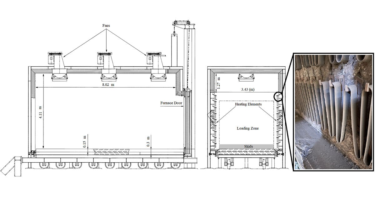
Material and experimental benchmark: The load material is high-strength medium-carbon steel typical of heavy forging practices. This steel grade is commonly used for heavy-duty shafts, rolls, dies, and pressure-retaining parts in sectors such as transportation, mining, and power generation. Consistent tempering at the block scale is therefore essential to meet toughness and fatigue requirements in service. Plant trials with 29 metric-ton blocks were instrumented using embedded K-type thermocouples at selected faces and depths. These time histories across a full tempering cycle served as the validation baseline for the numerical model, ensuring that subsequent design exploration remained grounded in production-scale behavior.
Layouts and Coverage of Heating Elements Considered for Evaluation
A three-dimensional, industrial-scale model resolved forced convection from fans, together with wall radiation and heat conduction within the load. The model was driven by measured electrical energy consumption histories (kWh) and included wall heat-loss estimates. Temperature-dependent thermophysical properties of the steel were included to realistically represent its behavior during heating. Model predictions were compared against the instrumented blocks over an entire cycle, showing close agreement at corresponding locations. Once validated, the analysis proceeded in two phases.
Phase 1. Layout screening: Four practical placements were evaluated, as shown in Figure 1:
- Heating elements on two opposing side walls;
- Heating elements on all four side walls;
- Heating elements on all four side walls plus the ceiling; and
- Heating elements on the ceiling only.
Each layout balances direct radiation, recirculation patterns, and exposure of stacked blocks differently.
Phase 2. Coverage optimization: The most promising layout from Phase 1, elements on two opposing side walls, was retained. The fraction of each side wall covered by the elements was then varied from low to high. Polynomial response surfaces captured how the three thermal performance metrics and one time metric change with coverage, and multi-objective searches identified coverage bands that jointly minimize these metricsdes de couverture qui minimisent conjointement ces mesures.
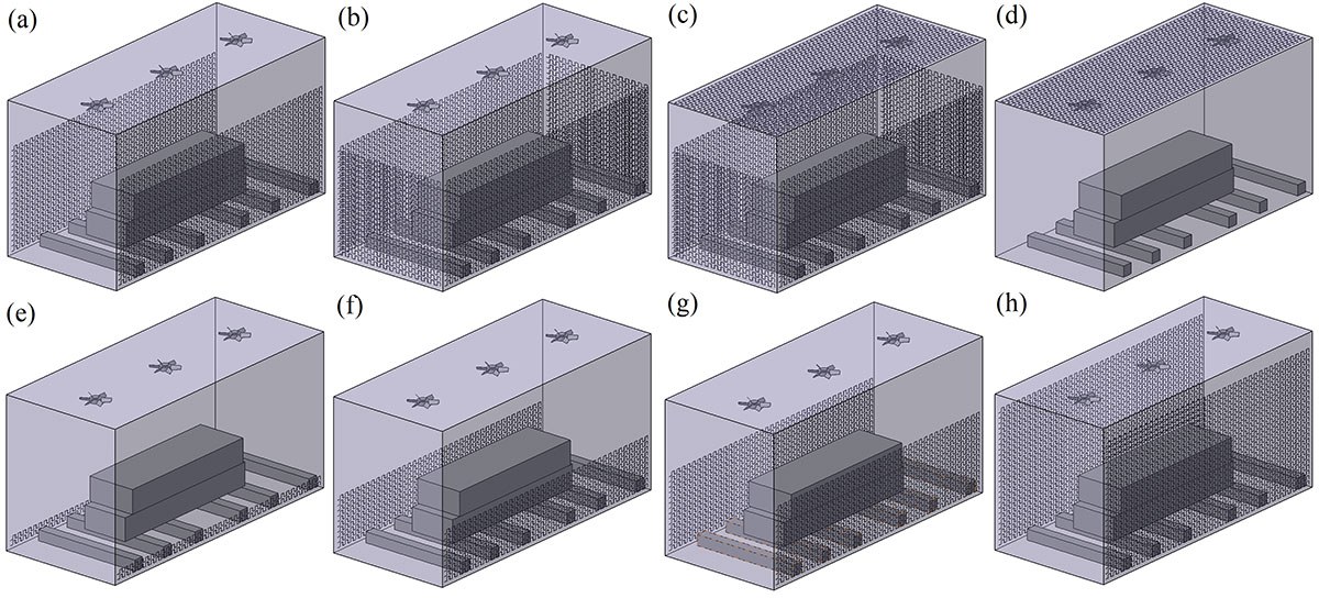
Figure 1. Evaluated layouts for heating elements
Optimum Configuration of Heating Elements
Layout screening: Installing elements on two opposing side walls produced the lowest surface non-uniformity and smallest surface-to-center differentials as opposed to installing the elements on all walls or adding to the ceiling. Surrounding the chamber or including the ceiling accelerated early heating but amplified spatial non-uniformities. Configurations with the ceiling yielded the largest center-to-center differences between stacked blocks because of top-biased exposure and altered recirculation.
Coverage optimization: In the two side-wall arrangement, lower surface coverage outperformed the high-coverage industrial baseline, as shown in Figure 2. Independent optimizers converged on a low-coverage band, approximately one-tenth to one-seventh of each side wall, as optimal. Relative to the baseline, this band:
- Reduced maximum surface non-uniformity by about 4 to 8%;
- Reduced surface-to-center differentials by about 5 to 6%; and
- Reduced center-to-center differences between stacked blocks by about 66 to 71%.
Mid-cycle cross sections showed more homogeneous mid-thickness fields and closer block-center temperatures at low coverage, indicating improved batch consistency.
Physical interpretation: Very high coverage increases the fraction of faces receiving intense direct radiation simultaneously, promoting steeper, uneven gradients. The low coverage band distributes energy more gradually and allows circulation to balance exposure, yielding smoother through-thickness profiles and better agreement between stacked blocks.
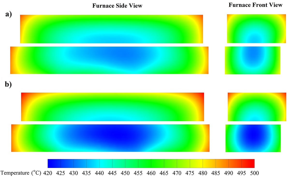
Figure 2. Temperature contours of loaded blocks at the central cross section at t = 50,000 s (one-third of the total process duration): (a) 10% and (b) 70% of each side wall covered by elements.
Why it Matters (Practical Impact)
These findings provide a practical, low-capital adjustment for electric heat treatment. Instead of adding elements on more walls or the ceiling, reducing side-wall coverage (by removing rows) tightens temperature histories across large blocks and can help shorten stabilization at the holding temperature. The same CFD-validated, surrogate-guided, multi-objective workflow can be applied to other electric furnaces and loading patterns to tune element layouts while protecting property targets, and maintaining control over energy use and cycle time.
Energy and cost context: A typical tempering cycle in this industrial furnace consumes about 8 to 10 MWh of electricity. Based on Hydro-Québec’s Rate L energy charges, which depend on the yearly contract, this corresponds to roughly $295 to $370 per cycle for the energy component alone (excluding demand charges). With a peak electrical capacity of 2.16 MW per furnace, any reprocessing triggered by non-uniformity would repeat the same energy use and costs while reducing furnace availability and adding avoidable emissions. Lowering thermal variability reduces the risk of such reprocessing and the associated financial and environmental penalties.
Limitations & Next Steps
Conclusions focus on a single, high-leverage variable (side-wall surface coverage) in one validated furnace and loading configuration. Other variables (element spacing patterns, door leakage, and fan schedules) were kept constant. The optimization relied on polynomial surrogates of four metrics, three thermal and one time. Including additional objectives (e.g., energy per batch) could shift the precise optimum. A logical next step is to extend the research to hybrid wall-and-ceiling patterns and alternative distributions, vary fan control strategies, and to link improved thermal uniformity to measured metallurgical outcomes (hardness maps and microstructures) in the same high-strength medium-carbon steel blocks used for validation.
Additional Information
For more information on this research, please read the following paper: Sajad Mirzaei, Nima Bohlooli Arkhazloo, Jean-Benoit Morin, Mohammad Jahazi, Influence of heating elements layout on temperature uniformity in a large size heat treatment furnace, Case Studies in Thermal Engineering, Volume 61, 2024, 105062, ISSN 2214-157X,