November 18, 2026
Timers in Electronic Circuits
Every electronic chip requires a timer to synchronize its operation. In modern integrated chips, this timer is a mechanical resonator — a structure that vibrates at a defined frequency, providing a precise sinusoidal signal. This signal acts as the clock for every electronic component and is therefore an essential feature.

Figure 1 -Each integrated circuit chip has a tiny clock acting as the heartbeat to synchronize the operation of its components
Quartz and MEMS Timing Components
For the last 100 years, quartz crystals have been the preferred mechanical resonators for timing applications due to their exceptional mechanical performance and resilient frequency stability. However, with the rapidly shrinking electronic devices such as smartwatches, wireless earbuds, biological implants, etc., the bulky size of quartz poses an obstacle to the miniaturization of electronic chips [1]. Another technology called microelectromechanical system (MEMS) resonators is therefore being considered as a potential replacement in timing applications. However, owing to its excellent mechanical performance and long history, replacing quartz has proven to be anything but simple. Therefore, research efforts are dedicated to matching quartz-level mechanical performance on MEMS platforms.
TPoS MEMS
The MEMS technology used in our study is called thin-film piezoelectric resonators on substrate (TPoS), in which a thin layer of a piezoelectric material such as aluminum nitride is used to excite a much thicker silicon layer. These structures are obtained through conventional micro-fabrication techniques used in making ubiquitous electronic chips. They provide benefits such as reduced per-unit costs and higher integration capability with other electronic components [1].
Drawbacks of MEMS Resonators
A major drawback of size shrinkage in MEMS resonators is the reduced capacity for available energy storage. Hence, one major obstacle for TPoS MEMS is their lower energy efficiency compared to quartz, which is characterized by the quality factor (Q) of the output signal. Q measures how close the real resonator is to an ideal resonator. In a real resonator, the resonance peak forms a “skirt” around its otherwise sharp resonance frequency due to various energy dissipation sources. This reduced sharpness resonance can curtail the precise synchronization that these devices must enable in the circuits they are deployed into. This concept of Q is illustrated in Figure 2 using the working principle of a MEMS resonator.
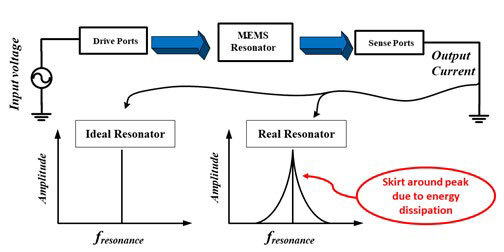
Figure 2 Working principle of a MEMS resonator and the concept of quality factor as a measure of energy dissipation
A high Q means that the resonator exhibits less energy dissipation and high energy storage, resulting in a low-noise signal and a more stable resonant frequency.
A High-Performance MEMS Resonator
In this work, we proposed to increase the energy storage capacity by mechanically coupling additional masses to increase the overall potential energy. The design flow for this work is shown in Figure 3. It starts with a TPoS MEMS disk resonator, shown in (a), which has been mechanically coupled, in (b), to 4 smaller disks around its periphery. This increases the available potential energy. To ascertain how the Q scales, we then proposed a third variant featuring 12 of these small disks, as shown in Figure 3(c).
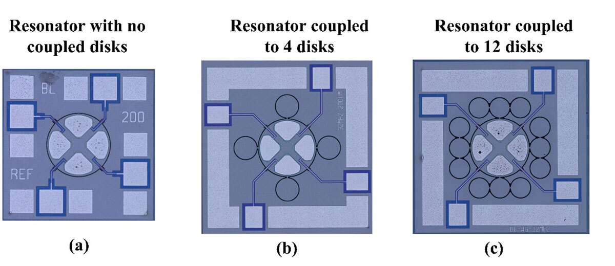
Figure 3. Coupling of mechanical structures to enhance the stored energy, and thus the quality factor of MEMS resonators. Optical micrographs of the fabricated resonators repurposed from the author’s published works [3], [4]
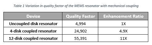
The structures were designed via simulations for optimum energy storage and then fabricated using a commercial MEMS fabrication platform. The resonance peaks of the fabricated devices were measured experimentally using a vector network analyzer. Table 1 shows the influence of the coupled disks on the measured Q of the MEMS resonator. It was observed that the Q increment is almost proportional to the number of appended disks. Hence, a near 11X factor of enhancement was observed for the 12-disk coupled variant of the MEMS resonator.
Conclusion
In conclusion, this article encompassed conceptualization, design, and experimental validation of a Q enhancement methodology for MEMS resonators via mechanical coupling. The concept can be used in MEMS resonators as a drop-in replacement for quartz in timing applications. This research provides avenues for smaller and power-efficient electronic components while maintaining optimum performance in terms of speed and precision.
References
[1] R. Abdolvand, B. Bahreyni, J. Lee, and F. Nabki, “Micromachined Resonators: A Review,” Micromachines, vol. 7, no. 9, p. 160, Sep. 2016, doi: 10.3390/mi7090160.
[2] R. Abdolvand, H. Lavasani, G. Ho, and F. Ayazi, “Thin-film piezoelectric-on-silicon resonators for high-frequency reference oscillator applications,” IEEE Trans. Ultrason., Ferroelect., Freq. Contr., vol. 55, no. 12, pp. 2596–2606, Dec. 2008, doi: 10.1109/TUFFC.2008.976.
Additional Information
For more detail on this work, readers can refer to the following published articles from the authors:
[3] S. T. Balghari, A. Ali, M. Gratuze, and F. Nabki, “Mechanical Mode Coupled Piezo-on-Silicon Bulk Acoustic Wave MEMS Resonators in Tank Configuration for Q-Enhancement,” Journal of Microelectromechanical Systems, pp. 1–15, 2025, doi: 10.1109/JMEMS.2025.3643897.
[4] A. Ali, S. Tariq Balghari, M. Wajih Ullah Siddiqi, and F. Nabki, “Reduction of Motional Resistance Using Piezoelectric on Silicon MEMS Disk Arrays for Ambient Air Applications,” Journal of Microelectromechanical Systems, pp. 1–13, 2025, doi: 10.1109/JMEMS.2025.3571721.