December 10, 2025

Introduction
Hydro-Québec, a parapublic corporation founded in 1944, operates a vast network of more than 262,000 km of power lines across Quebec. A significant portion of its infrastructure is aging, resulting in growing maintenance requirements. Some critical parts are no longer available from suppliers, posing challenges in terms of supply and lead times. To reduce replacement costs and speed repairs, Hydro-Québec is replicating and optimizing systems to enhance the resilience of its network and reduce its dependence on external suppliers.
As part of a final-year mechanical engineering project, Hydro-Québec proposed analyzing the bearing support of an old high-voltage disconnect system, whose initial design had never been reevaluated since it was commissioned. This component in the assembly experienced numerous failures in the past and is no longer supported by Kearney. There are more than 150 of these systems still in operation in the network. Hydro-Québec has identified defects in these high voltage switches, located at the legs and end stops. The complete Kearney disconnector assembly is shown in Figure 1 (I) and its critical component, bearing support, with overall dimensions of 343 x 383 x 207 mm is shown in Figure 1 (II).
The purpose of this article is to present the reverse engineering process used to analyze the switch assembly. This is to identify the causes of the bearing support failure and propose improvements for its remanufacturing.
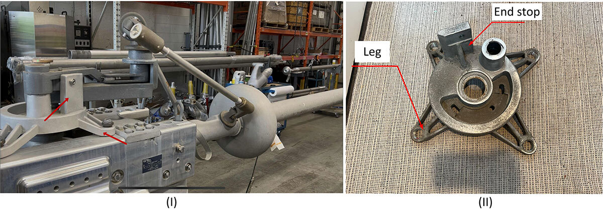
Figure 1 Kearney high voltage disconnect switch: (I) Mechanical assembly; (II) Bearing support (red arrows indicate failure locations)
High-Voltage Disconnect Switch
A disconnect switch is a mechanical device used to isolate an electrical circuit, notably in Hydro-Québec's high-voltage power transmission facilities. Its main role is to disconnect power from a power line, to ensure maintenance crews can work safely.
The switch operates using a conductive blade that provides electrical contact between two poles located at its ends and two springs that compensate for the weight of the blade when the system is activated. When the blade is parallel to the ground, it is in the off position. Its poles are then aligned with the high-voltage electrical contacts, allowing current to flow normally through the circuit (Figure 2; I). At this precise moment, the springs are compressed to their maximum. To open the circuit, an operator on site activates a handwheel connected to a gearbox, which rotates the blade 90 degrees on its axis (Figure 2; II). This rotation disconnects the blade from the poles, interrupting the flow of current. However, to ensure complete insulation and avoid any risk of electric arcing, the operator must continue to turn the wheel until the blade reaches a 91° angle to the horizontal (Figure 2; III, IV). At this point, as the blade rises, the springs gradually decompress until they no longer compensate for the blade's weight. (Note that the springs, gearbox, and flywheel are not shown in the images in Figure 2.)
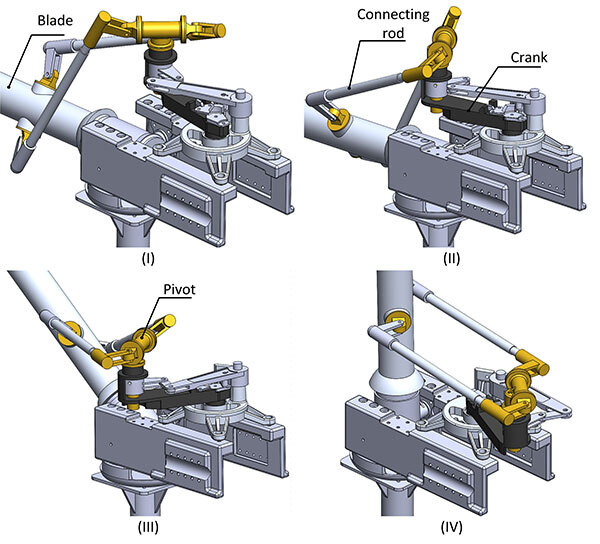
Figure 2 High voltage disconnect switch travel: (I) Closed circuit (current flowing); (II) Open circuit (current no longer flowing); (III) Intermediate path; (IV) Completely isolated circuit (secure)
Reverse Engineering Steps
The reverse engineering process used in this study involved several steps. It began with the reconstruction of the bearing support geometry. Then, an in-depth characterization was performed to identify the material and manufacturing processes used, detect manufacturing defects, and measure the material's mechanical properties. Next, the functional relationships between the switch subsystems were analyzed to determine the loads applied to the bearing support and calculate the stresses generated throughout the disconnecting operation. The safety factor of the bearing support was then calculated, and an improved design was proposed. A comparative analysis of manufacturing processes was then conducted, taking into account costs and environmental impacts, to guide decision-making regarding future production. Finally, engineering drawings were prepared, including the tolerances required to reproduce the bearing support.
Geometry
The digital reconstruction of the bearing support was carried out using a Hexagon 3D scanner, PolyWorks and CATIA software. This step produced a 3D model of the part, which was needed for structural analysis and manufacturing drawings. The geometry modelling was carried out in four distinct stages: (I) 3D scanning; (II) creating primitives; (III) CAD; and (IV) comparing CAD and 3D scanning (Figure 3). Note that the maximum deviations between the CAD and the point cloud resulting from 3D scanning did not exceed 1 mm, except for repaired or altered surfaces.
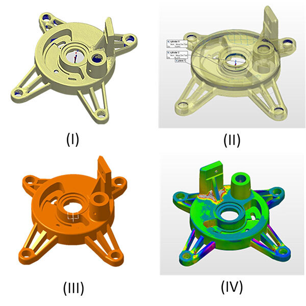
Figure 3 Reconstruction steps: (I) Digitizing; (II) Creating primitives; (III) CAD; (IV) Comparing CAD and 3D scanning
Material and Manufacturing Process
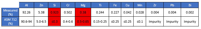
An in-depth analysis was conducted to identify the nature of the material, detected manufacturing defects, and measured the mechanical properties of the bearing support material. An X-ray spectroscope, CT scanner, hardness tester, and tensile testing machine were used to perform this analysis. The results were compared with technical data and applicable standards. First, X-ray spectroscopy was used to identify the alloy in the manufactured part (Table 1).
Table 1 Comparison between the aluminum alloy elements in the bearing support and the data from ASM 712
Next, a simple visual inspection helped identify the initial manufacturing process. It was sand-casting. Now that the manufacturing process was identified, an X ray analysis of the legs was conducted to determine the quantity, size, and type of inherent discontinuities present in that critical area. Due to size limitations of the CT scan used, the legs were sectioned prior to the inspection. Figure 4 shows the manufacturing defects detected in the bearing support legs. These porosities and shrinkage voids could affect the strength of the part (this hypothesis will be verified in the following stages of this study).
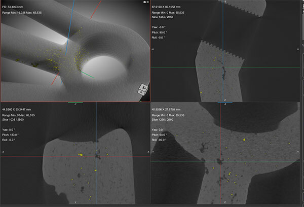
Figure 4 Casting defects (shrinkage cavities and pores)
Subsequently, we performed nine hardness tests and four tensile tests to verify whether the deviations in the chemical composition of the material from the ASM values had an impact on its mechanical properties (see Table 2 for values). The tensile test specimens were manufactured from the end stop of the bearing support (Figure 1 (II)).
Table 2 Comparison of the mechanical properties of the bearing support with the ASM 712 data.
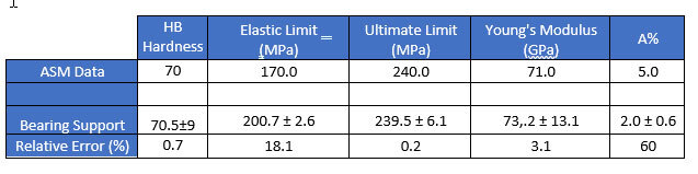
Hardness tests showed that the average values obtained comply with ASM specifications. Furthermore, tensile tests determined that mechanical strength was not significantly affected by deviations in the alloy's chemical composition from the ASM technical data. However, elongation at break was affected. Furthermore, the significant variations observed in elongation values (A%) are likely due to manufacturing defects, indicating a high degree of heterogeneity in mechanical properties. This variability could compromise the reliability of the working part.
Load Cases and Mechanical Stresses
To analyze this mechanical system, a complete model of the switch assembly was created in SolidWorks to identify the centers of gravity and dimensions required for static analysis. Next, free-body diagrams (FBDs) (Figure 5) and equilibrium equations were established for each 10° increment of blade rotation.
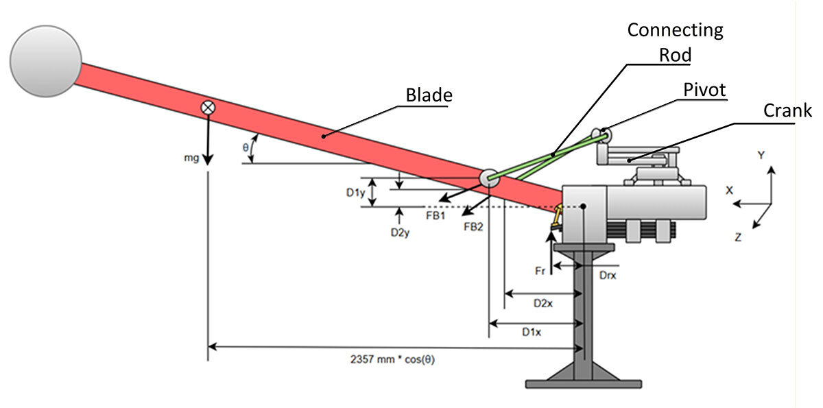
Figure 5 Kearney DCL high voltage disconnect switch
By applying the static equilibrium equations determined previously, the forces and the moments generated by the blade and the springs were transferred to the bearing support. Figures 6 and 7 show the variations in the resulting forces and moments in relation to the blade angle.
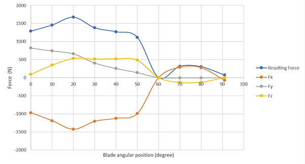
Figure 6 Graph of the forces exerted on the crank in relation to the blade angle

Figure 7 Graph of the resulting moments at the crank in relation to the blade angle
The graphs reveal two key moments in the operation of the switch. At 20°, the resulting force and moment are at their maximum at the crank. These values gradually decrease up to 60°, as the spring compensates less and less for the weight of the blade. Beyond 60°, the resulting force and moment increase again, as the system must then bear the entire weight of the blade.
Next, finite element analyses and a convergence analysis were performed using Ansys (Figure 8 (I)) to evaluate the appropriate mesh and determine the mechanical behaviour of the bearing support, in particular the stresses in the legs in relation to the blade angle when the switch is activated (Figure 8 (II).
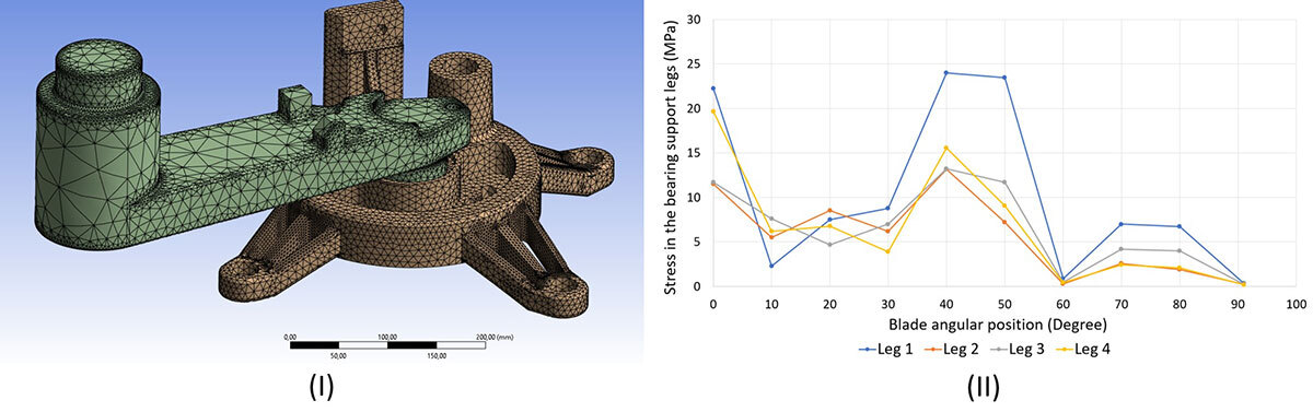
Figure 8 Finite element analysis results; (I) Mesh used; (II) Stresses in the legs as functions of the blade angular position
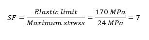
These results showed that the maximum stress in the legs occurs when the blade is tilted at 40° to the ground. The stress reaches 24 MPa, which corresponds to a safety factor of 7 for this critical area (note that the elastic limit used in this calculation was determined by mechanical tests carried out beforehand).
This result leads to the conclusion that the fractures observed in the bearing support legs are not attributable to design errors, but rather to defects in the casting process.
Revision: Design and Shaping
To further improve the design of the bearing support, especially at the legs, topological optimization was performed using Ansys software. The results led to the creation of a new model, reorienting its geometry according to the recommendations of this optimization (Table 3).
Table 3 Comparison between the initial design and the improved design
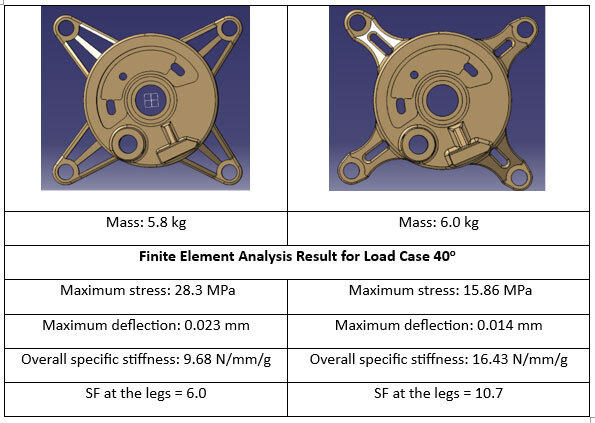
The new bearing support design resulted in a 3.44% increase in weight due to the increased thickness of the stiffener and the addition of fillets and material to the legs. These adjustments reduced the maximum stress by 43.5%, bringing the safety factor to 11. This suggests a very high level of reliability, which is important given the harsh operating conditions. In addition, reorienting the material in the legs improved specific stiffness by 41%, demonstrating superior mechanical performance compared to the initial model. Time constraints prevented us from exploring other design options that could have further optimized the bearing support design, by decreasing the weight while maintaining a reasonable safety factor.
Economic and Environmental Analysis
To begin the economic analysis, a drawing of the initial part was created and sent to manufacturers to obtain quotes. Functional tolerances were calculated, as well as the precise location of drill holes and taps, to ensure that the drawings met assembly requirements. Figure 9 shows the manufacturing drawing of the bearing support.
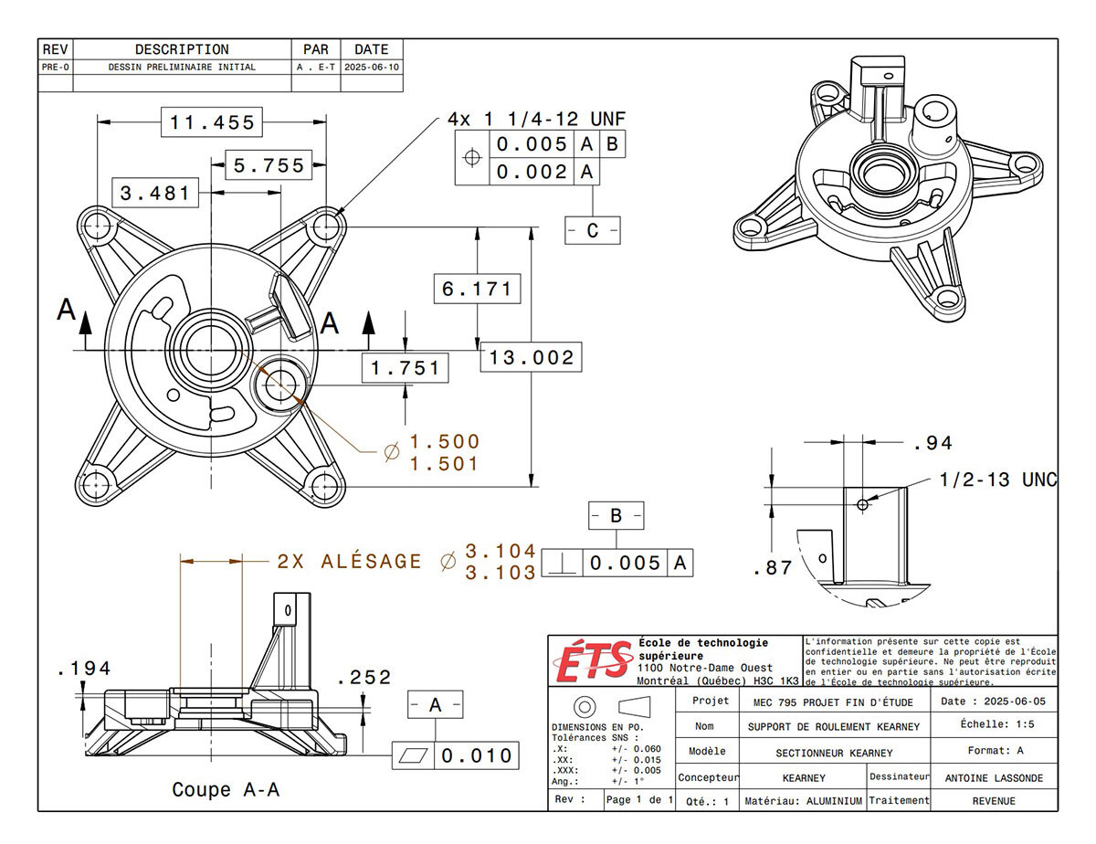
Figure 9 Drawing of the bearing support with functional tolerances
To resume production of the bearing support in accordance with the initial design, three processes were analyzed and compared in terms of economic and environmental factors: machining, sand casting, and laser powder bed fusion (LPBF) additive manufacturing. The economic analysis was based on quotes from several suppliers. Production costs for 10 units were converted into average costs per unit to compare processes, where profitability varies depending on the production volume. Figure 10 shows the results:
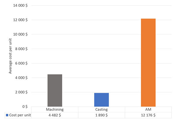
Figure 10 Average cost per unit based on the manufacturing process (series of 10 units)
Figure 10 shows that additive manufacturing has a higher unit cost than machining and casting. However, these traditional processes generate more material waste, making them less environmentally friendly.
The subsequent study will therefore focus on a simplified life cycle analysis of each process in order to compare their environmental performance using a single impact indicator: greenhouse gas emissions expressed in kg CO2 eq. The life cycle analysis was performed using Simapro software, based on the Ecoinvent V3.11 database. The impact assessment method used for the analysis was IPCC GWP 100, available in Simapro. This method made it possible to assess the environmental impact of the compared solutions in terms of their contribution to climate change. Although it reduced the impact to a single category, this approach was relevant in our context of analysis and decision-making. The different shaping processes were compared based on their CO₂ equivalent emissions, taking into account material losses (metal, tools, sand, etc.), energy consumption, transport, and other relevant parameters. The end-of-life management phase was not considered due to its uncertainty. Therefore, the comparison only covers emissions related to the production of the bearing support. Figure 11 shows the results based on the process and the volume of units produced.
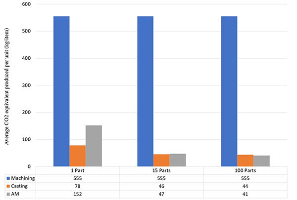
Figure 11 Average CO2 equivalent emissions based on the manufacturing process and the quantity of bearing supports manufactured
The graph in Figure 11 shows that casting generates the least CO₂ eq for a single unit, as some of the metal from the risers can be reused. Additive manufacturing generates more CO₂ equivalent emissions when producing the first unit, mainly due to the atomization step required to manufacture metal powders. However, powder that is not used during printing can be reused almost entirely, which helps reduce material waste. Machining remains the most polluting process due to its significant material losses. Regardless of the number of units produced, CO₂ eq emissions remain constant for the machining process. Note that to obtain an aluminum unit with a final mass of approximately 6 kg, the initial raw material mass was 70 kg. Only 8.5% of the initial stock will be used due to the shape of the part. This study shows that additive manufacturing has good environmental potential, while machining is more economical. As for casting, this process offers a good compromise, combining low environmental impact with moderate implementation costs. However, if the design of the bearing support is significantly modified in the future, a new life cycle analysis should be carried out to validate the results.
Conclusion
To conclude, reverse engineering requires significant resources and specialized skills in identifying causes of failures and optimizing part design. In this study, the repeated breakages were not the result of a design flaw, but rather insufficient quality control during manufacturing. To prevent these non-conformities related to shaping and alloying, it is imperative to strengthen quality control processes and incorporate detailed technical specifications into contract clauses. However, this study did not allow to determine the preferred manufacturing process, due to insufficient economic data allowing for a thorough comparison of options and evaluating different supply scenarios. Our analysis has been forwarded to the Gatineau and Lévis workshops, where the reverse engineering approach will be used to guide their decisions regarding remanufacturing of the bearing support, as well as a basis for future reverse engineering approaches.